DJ Bonebraker
a.k.a Laura
Part I: Making the Darn Model.
This tutorial will guide you through the steps required to make a fairly simple 18th century cannon model in Bryce 5, as well as prepare the model for animation. Even though this model is fairly simple, the processes and techniques for making this model are exactly the same as what's used for more complicated designs (you'll just have to make more of the same things).
First, create a new document in Bryce 5. Move the mouse pointer until the main menubar appears at the top of the screen. Click on "File" and then select "Document Setup." In the document setup, change the Document Aspect Ratio to 1:1, the document Resolution to 640x640, and make sure that AntiAliasing is selected for Superfine. Click the checkmark to close the setup window, and you're now ready to start modeling.
To create the gun mount, first make sure that the Create tools are selected, and click on the cube to create a cube. Since the Cube, which should be called "cube 1," is already selected, there should be a series of small icons to the right of the object. Click on the "A" icon (top icon box) to edit the attributes. In the top part of the General Attributes are a series of options for boolean editing, and by default "neutral" is selected. Change this setting to "positive." Below the boolean settings are a series of numbers that determine the overall dimensions of the object and its position in Bryce space. Go to the Size boxes, and change the x value to 10, the Y value to 10 and the Z value to 20. Now go to the Origin boxes, and assign 0 to the X and Z values, and 8 for the Y value. Press ENTER or click on the checkmark to close the attribute window and verify your changes, and you now should have an elongated box floating above the ground plane.
To texture the object, click on the "M" icon. Once in the Materials window, click on the arrow at the top righthand corner of the material preview, which will open up your Bryce 5 pre-set materials libraries. Click on the "Simple&Fast" library, and scroll down until you find the wood grain textures. Either the Maple or the Cedar (the texture I used) will work nicely. select the texture, and click the check mark or hit enter to select, and the material will be set. Just click the check mark at the bottom of the material window or hit enter again to close the window and apply the selected texture to the object.
Now here come the somewhat tricky part. Go to the main menu (by moving your mouse to the top of the screen) and select "Edit" and then "Duplicate" which creates an exact duplicate of the selected object at the same exact position as the first. The new object is automatically selected, so edit its attributes, but this time change the boolean setting to "Negative," change the Origin to X=0, Y=12.25, and Z=2.25, and change the Size to X=11, Y=2.50, and Z=5.50, hit enter when done. There is no need to texture the object, since the textures were automatically copied during the duplication process. Now select both the first cube and the second cube by holding Ctrl and clicking on the first cube, and a list of selectable objects pops up. Since Cube 2 should already be selected, release the Ctrl key and and hold the Shift key while clicking on the "Cube 1." Now that both cubes are selected, there should be a new icon to the right of the objects that is labeled with a "G." This is the Grouping tool. All you have to do is click it, and the objects are now grouped. In the prieview window in the upper lefthand corner of the screen, you should now see that there is a gap in the first box that's the same size as the second box. By assigning a positive value to the first box, a negative value to the second box and grouping them, you've essentially told the program to subtract the second object's volume from the first object. This is known as boolean editing. If you want to do anything in Bryce, you'll be doing this a lot.
Now that you've created your first boolean, here's a quick way to finish off the gun mount: Select the negative object by holding Ctrl and clicking on the second box to bring up a list of objects as before. This time, simply release the Ctrl key and click on the "Cube 2" object, and that will de-select the group (which by default is called "Group 1") and highlight just the negative box. Duplicate the negative box as stated bofore, but change the Position and Size to 0,11.25,-5.25 for the Position, and 11,4.50,10.50 for the Size. If you didn't already notice, this duplicated object has automatically been included in the boolean group. This, ladies and gentlemen, saves a HUGE amount of time when working with complex designs. Now if you look at the preview window (particularly the side view) you should start to see that the cannon mount is starting to take shape. To put a cap on the base mount, simply duplicate the object currently selected, and change the position and dimensions to: 0,10,0 for the Position, and 5,7,22 for the size.
What you have, thus far, should look like this:

Now to move on to the next part of the model: the Wheels.
This stage is fairly simple. First create a cylinder, then assign the following values to it: Origin: X=0, Y=3, Z=7.5; Size: X=2, Y=17, Z=2; Rotate: X=0, Y=0, Z=90 degrees. For texture, go to the texture menu, open the preset library, and go to the "Metals" library. Select the "Cast Iron" texture and apply it to the object. Duplicate the cylinder, and change its Size to 6,2,6, and Origin to 6.5,3,7.5. Duplicate this object, and change the X value of the origin to -6.5. Select all three cylinders and group them. Go to the group's attributes, and change the name of the group to "Front Wheels" (this helps keep track of the objects for when you start animating). Now duplicate the group, and change the group's origins to 0,3,-7.5 and re-name this second group to "Rear Wheels."
Your cannon should now look like this:

The barrel and accompanying parts gets a wee bit complicated, so pay close attention. First create a torus, and rotate it 90 on the Y axis. Change the Size to 4.5,4.5,1.5 and the origin to 3.25,11,2.5. The texture used in this demonstration is the "Hammered Steel" preset found in the "Metals" section of the preset library. Duplicate this object, and change the X origin of the new torus to a -3.25. Now you have the clasps for securing the barrel done. For the Barell itself, first create a cylinder and make the rotation 90 deg on the Z axis, position it at 0,11,2.5, and change the Size to 2.5,9,2.5. Rename the cylinder to "Barrel Pin." The reason for this will be explained later. Edit the materials, and apply the "Hammered Steel" texture, however, instead of just applying it, we're going to play around with it a bit to make it look like that ol' black cannon steel. Change the diffuse color to a slightly darker grey, and the ambient color to an equally dark grey or brown color. Also, add the texture to the diffusion mapping by clicking on the circle in the "A" column. Your texture window should now look like this:

Before closing the window, click on the "copy" button below the preview, then either hit the Enter key or click on the checkmark.
Create a new cylinder and assign it a positive boolean value before moving it to an Origin of 0,10.5,0, rotating it 90 degrees along the X axis, and changing its Size to 5,20,5. To apply the previously copied texture, edit the material and click the "paste" button under the material preview, then press Enter or click the checkmark. Now duplicate the cylinder, and change its size to 4.5,5,4.5 and its position to 0,10.5,14.5. Duplicate this one, and where the toolbar is on the top of the screen, click "Edit" There should now be a seris of boxes representing various editing opetions, as well as a small Icon that looks like this: <--> Click the two arrows, and a list of the various objects that can be created in Bryce will pop up. Hold the mouse button and drag the cursor to the torus icon and release the button. You have now changed your cylinder to a torus. Edit the torus' attributes, and give it the following values: Rotate: 0,0,0; Origin: 0,10.5,12.5; Size:6,6,1. Duplicate this Torus, and assign these values: Change the Z Origin to 16.5, and the X and Y sizes to 5.5.
Duplicate this torus, and use the Edit tool to change the new object to a sphere. Change the Sphere's Z origin value to -7.5, and change the size to 5,5,5. Duplicate this spere, and change the Z Origin to -10.25, and change the Size to 2,2,2. Now one final bit for the Barrell: Select the first cylinder made for the barell (the one created AFTER the Barrel Pin cylinder was), and duplicate it. Make the new cylinder Nevgative, change its z position to 7.5, and reduce the X and Z values to 3.5. Select all these objects EXCEPT THE BARREL PIN CYLINDER AND THE FIRST TWO TORII MADE, and group them. Name the resulting group "Barrel" Edit the attributes of the "Barrel" group, and select the "Linking" tab. Click on the box below where it says "Object Parent Name" to display a list of linkable objects, and select the object you re-named "Barrel Pin" and press enter or click the check mark. Now, whenever you move or rotate the Barrel Pin, the rest of the Barrel will move with it.
For the final part of the model, Select the "Gun Mount" group, The "Front Wheels" and "Rear Wheels" groups, the Barrel Pin cylinder and the first two torii created and group them in one big group that we'll just call the "Carriage." The almost complete cannon should now look like this:

Now to get the cannon looking right, select the Barrel pin and change its y rotation to 10 degrees. If you didn't already, you'll have to clidk on the "General" attributes tab to hide the linking options and bring up the standard attribute editing options.
One last step, and your model will be ready to animate. Bring up the main menu, select "File" and "Document Setup," and change the Document Resolution to 140x140 (a good size for most Civ III units this size), and click on the check mark or press enter. Go to the Camera view. On the left side of the screen, just right of the zoom, trackball, and view controls are four downward pointing arrows. Click on the second arrow down from the top and it will bring up the camera menu. Select "Edit Current Camera..." to bring up the camera attribute menu. This menu should look familliar, since it's almost identical to the object attribute menu. Click on the Linking tab, and assign Plane 1 (the default ground plane) as both the Object Parent Name AND the Track Object Name. Click on the "General" tab, and change the origin to -4500, 3500, 4500, the FOV to 1 degree and the Scale to 150%. Finally, click on the "Sky and Fog" toolbar and enter the skylab by clicking on the small icon that looks like a cloud and rainbow. For Sun and Moon, put the sun controls at the bottom right corner and leave everything else alone. For the Cloud cover, deselect everything, leaving a blank blue box for the preview. For the Atmosphere setting, deselect everything except the Fog and Haze, and set BOTH those to 0 density. Now click on the arrow to the right of the preview box and click the Add button at the bottom left corner to add this sky to your preset skies, since you'll be using these settings for all your future units.
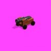
Congratulations, the unit is now ready to animate. The finished product should look like this:
This tutorial will guide you through the steps required to make a fairly simple 18th century cannon model in Bryce 5, as well as prepare the model for animation. Even though this model is fairly simple, the processes and techniques for making this model are exactly the same as what's used for more complicated designs (you'll just have to make more of the same things).
First, create a new document in Bryce 5. Move the mouse pointer until the main menubar appears at the top of the screen. Click on "File" and then select "Document Setup." In the document setup, change the Document Aspect Ratio to 1:1, the document Resolution to 640x640, and make sure that AntiAliasing is selected for Superfine. Click the checkmark to close the setup window, and you're now ready to start modeling.
To create the gun mount, first make sure that the Create tools are selected, and click on the cube to create a cube. Since the Cube, which should be called "cube 1," is already selected, there should be a series of small icons to the right of the object. Click on the "A" icon (top icon box) to edit the attributes. In the top part of the General Attributes are a series of options for boolean editing, and by default "neutral" is selected. Change this setting to "positive." Below the boolean settings are a series of numbers that determine the overall dimensions of the object and its position in Bryce space. Go to the Size boxes, and change the x value to 10, the Y value to 10 and the Z value to 20. Now go to the Origin boxes, and assign 0 to the X and Z values, and 8 for the Y value. Press ENTER or click on the checkmark to close the attribute window and verify your changes, and you now should have an elongated box floating above the ground plane.
To texture the object, click on the "M" icon. Once in the Materials window, click on the arrow at the top righthand corner of the material preview, which will open up your Bryce 5 pre-set materials libraries. Click on the "Simple&Fast" library, and scroll down until you find the wood grain textures. Either the Maple or the Cedar (the texture I used) will work nicely. select the texture, and click the check mark or hit enter to select, and the material will be set. Just click the check mark at the bottom of the material window or hit enter again to close the window and apply the selected texture to the object.
Now here come the somewhat tricky part. Go to the main menu (by moving your mouse to the top of the screen) and select "Edit" and then "Duplicate" which creates an exact duplicate of the selected object at the same exact position as the first. The new object is automatically selected, so edit its attributes, but this time change the boolean setting to "Negative," change the Origin to X=0, Y=12.25, and Z=2.25, and change the Size to X=11, Y=2.50, and Z=5.50, hit enter when done. There is no need to texture the object, since the textures were automatically copied during the duplication process. Now select both the first cube and the second cube by holding Ctrl and clicking on the first cube, and a list of selectable objects pops up. Since Cube 2 should already be selected, release the Ctrl key and and hold the Shift key while clicking on the "Cube 1." Now that both cubes are selected, there should be a new icon to the right of the objects that is labeled with a "G." This is the Grouping tool. All you have to do is click it, and the objects are now grouped. In the prieview window in the upper lefthand corner of the screen, you should now see that there is a gap in the first box that's the same size as the second box. By assigning a positive value to the first box, a negative value to the second box and grouping them, you've essentially told the program to subtract the second object's volume from the first object. This is known as boolean editing. If you want to do anything in Bryce, you'll be doing this a lot.
Now that you've created your first boolean, here's a quick way to finish off the gun mount: Select the negative object by holding Ctrl and clicking on the second box to bring up a list of objects as before. This time, simply release the Ctrl key and click on the "Cube 2" object, and that will de-select the group (which by default is called "Group 1") and highlight just the negative box. Duplicate the negative box as stated bofore, but change the Position and Size to 0,11.25,-5.25 for the Position, and 11,4.50,10.50 for the Size. If you didn't already notice, this duplicated object has automatically been included in the boolean group. This, ladies and gentlemen, saves a HUGE amount of time when working with complex designs. Now if you look at the preview window (particularly the side view) you should start to see that the cannon mount is starting to take shape. To put a cap on the base mount, simply duplicate the object currently selected, and change the position and dimensions to: 0,10,0 for the Position, and 5,7,22 for the size.
What you have, thus far, should look like this:
Now to move on to the next part of the model: the Wheels.
This stage is fairly simple. First create a cylinder, then assign the following values to it: Origin: X=0, Y=3, Z=7.5; Size: X=2, Y=17, Z=2; Rotate: X=0, Y=0, Z=90 degrees. For texture, go to the texture menu, open the preset library, and go to the "Metals" library. Select the "Cast Iron" texture and apply it to the object. Duplicate the cylinder, and change its Size to 6,2,6, and Origin to 6.5,3,7.5. Duplicate this object, and change the X value of the origin to -6.5. Select all three cylinders and group them. Go to the group's attributes, and change the name of the group to "Front Wheels" (this helps keep track of the objects for when you start animating). Now duplicate the group, and change the group's origins to 0,3,-7.5 and re-name this second group to "Rear Wheels."
Your cannon should now look like this:
The barrel and accompanying parts gets a wee bit complicated, so pay close attention. First create a torus, and rotate it 90 on the Y axis. Change the Size to 4.5,4.5,1.5 and the origin to 3.25,11,2.5. The texture used in this demonstration is the "Hammered Steel" preset found in the "Metals" section of the preset library. Duplicate this object, and change the X origin of the new torus to a -3.25. Now you have the clasps for securing the barrel done. For the Barell itself, first create a cylinder and make the rotation 90 deg on the Z axis, position it at 0,11,2.5, and change the Size to 2.5,9,2.5. Rename the cylinder to "Barrel Pin." The reason for this will be explained later. Edit the materials, and apply the "Hammered Steel" texture, however, instead of just applying it, we're going to play around with it a bit to make it look like that ol' black cannon steel. Change the diffuse color to a slightly darker grey, and the ambient color to an equally dark grey or brown color. Also, add the texture to the diffusion mapping by clicking on the circle in the "A" column. Your texture window should now look like this:
Before closing the window, click on the "copy" button below the preview, then either hit the Enter key or click on the checkmark.
Create a new cylinder and assign it a positive boolean value before moving it to an Origin of 0,10.5,0, rotating it 90 degrees along the X axis, and changing its Size to 5,20,5. To apply the previously copied texture, edit the material and click the "paste" button under the material preview, then press Enter or click the checkmark. Now duplicate the cylinder, and change its size to 4.5,5,4.5 and its position to 0,10.5,14.5. Duplicate this one, and where the toolbar is on the top of the screen, click "Edit" There should now be a seris of boxes representing various editing opetions, as well as a small Icon that looks like this: <--> Click the two arrows, and a list of the various objects that can be created in Bryce will pop up. Hold the mouse button and drag the cursor to the torus icon and release the button. You have now changed your cylinder to a torus. Edit the torus' attributes, and give it the following values: Rotate: 0,0,0; Origin: 0,10.5,12.5; Size:6,6,1. Duplicate this Torus, and assign these values: Change the Z Origin to 16.5, and the X and Y sizes to 5.5.
Duplicate this torus, and use the Edit tool to change the new object to a sphere. Change the Sphere's Z origin value to -7.5, and change the size to 5,5,5. Duplicate this spere, and change the Z Origin to -10.25, and change the Size to 2,2,2. Now one final bit for the Barrell: Select the first cylinder made for the barell (the one created AFTER the Barrel Pin cylinder was), and duplicate it. Make the new cylinder Nevgative, change its z position to 7.5, and reduce the X and Z values to 3.5. Select all these objects EXCEPT THE BARREL PIN CYLINDER AND THE FIRST TWO TORII MADE, and group them. Name the resulting group "Barrel" Edit the attributes of the "Barrel" group, and select the "Linking" tab. Click on the box below where it says "Object Parent Name" to display a list of linkable objects, and select the object you re-named "Barrel Pin" and press enter or click the check mark. Now, whenever you move or rotate the Barrel Pin, the rest of the Barrel will move with it.
For the final part of the model, Select the "Gun Mount" group, The "Front Wheels" and "Rear Wheels" groups, the Barrel Pin cylinder and the first two torii created and group them in one big group that we'll just call the "Carriage." The almost complete cannon should now look like this:
Now to get the cannon looking right, select the Barrel pin and change its y rotation to 10 degrees. If you didn't already, you'll have to clidk on the "General" attributes tab to hide the linking options and bring up the standard attribute editing options.
One last step, and your model will be ready to animate. Bring up the main menu, select "File" and "Document Setup," and change the Document Resolution to 140x140 (a good size for most Civ III units this size), and click on the check mark or press enter. Go to the Camera view. On the left side of the screen, just right of the zoom, trackball, and view controls are four downward pointing arrows. Click on the second arrow down from the top and it will bring up the camera menu. Select "Edit Current Camera..." to bring up the camera attribute menu. This menu should look familliar, since it's almost identical to the object attribute menu. Click on the Linking tab, and assign Plane 1 (the default ground plane) as both the Object Parent Name AND the Track Object Name. Click on the "General" tab, and change the origin to -4500, 3500, 4500, the FOV to 1 degree and the Scale to 150%. Finally, click on the "Sky and Fog" toolbar and enter the skylab by clicking on the small icon that looks like a cloud and rainbow. For Sun and Moon, put the sun controls at the bottom right corner and leave everything else alone. For the Cloud cover, deselect everything, leaving a blank blue box for the preview. For the Atmosphere setting, deselect everything except the Fog and Haze, and set BOTH those to 0 density. Now click on the arrow to the right of the preview box and click the Add button at the bottom left corner to add this sky to your preset skies, since you'll be using these settings for all your future units.
Congratulations, the unit is now ready to animate. The finished product should look like this:
")

 )
)