Openfx step by step tutorial

Is my tutorial helpful

  • Yes, make another one just like it

    Votes: 14 50.0%
  • Yes but work more on the step by step part

    Votes: 8 28.6%
  • I've seen better

    Votes: 2 7.1%
  • it needs help

    Votes: 3 10.7%
  • it was horrible

    Votes: 1 3.6%

  • Total voters
    28

polyphemus

join the long blue line
Joined
Jun 14, 2005
Messages
1,202
Location
At the Air Force Academy
This is a tutorial on how to create and animate Units in Openfx followed by how to add the unit into CIVIII using FLICster.

Here it is finally. There are two links, simply download both links since the file is split in two. The second part is preceded by the first. Once downloaded, paste the second doc at the end of teh first so that the links in the table of contents can work.

You also need to grap the attached maps (texture files)

part 1
part 2


If you dont want to download then I also included the tutorila online :D (but it lacks some pics)
You need the attached file (maps.zip) to file the tutorial either way.

TOOLS USED: Openfx
Paint shop Pro and Animation Shop (comes with PSP)
FLICster

As always this tutorial is not for me since i already know how to do all this. It is for you so please help me make this better by posting comments and questions. Depending on poll results i might post Part 2 of this tutorial series which is where i will show you how to design a plane followed by a tutorial on animating the plane (depending on poll results)


EDIT: WHEN YOU GET THE PALETTE PART OF THIS TUTORIAL REFERENCE MY PEDIT TUTORIAL IN MY SIG, THE WAY DESCRIBED HERE IS AN OPTION BUT REDERD OBSOLETE WITH THE PEDIT PROGRAM
 

Attachments

  • maps.zip
    14.6 KB · Views: 805
not any more :lol:
 
How to Create and Animate Units with Openfx, Step by step


BY: Polyphemus

How To Design and Animate a Unit With Openfx

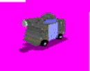
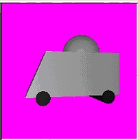
For this Tutorial I am going to use the Muffin Tank (previously created by Muffin, but modified by me).
Here is a pic of the tank:


You have to have FLICster, a 2D program that edits pcx files (I prefer Paint Shop Pro 8 which is what I will be using), Animation Shop (this program comes with PSP), Openfx, the attached camouflage color, and the blue color. Save them in Openfx>Maps>presets and [save it as Camo.gif and the blue one as blue.gif in Animation Shop]. Continue through all the optimizing prompts and then we shall continue. If all you want to do is Animate, then you don’t need FLICster or a pcx-editing program. But if you want to import your animation into civilization then you will need all of the above to follow along with this tutorial. OK, all set. Now open the Designer. Go to Window>Show Open GL Shaded Viewer.
I APOLOGIZE IN ADVANCE IF SOME PICTURES DON’T COME OUT RIGHT

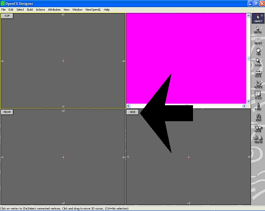
Then go to OpenGL>Preferences>Back Colour and choose Magenta. The viewer should then be displaying a Magenta background.

Next, go to shapes>Cube. Press ctrl+D to deselect all vertices. Now click the side button to view only the side.


Then, with the selector tool, select the two vertices on the left edge of the box.

With the move tool, move the two vertices to the left about half the cube in front of you.


Make sure that the box is straight. Press ctrl+A to select all of the vertices. With the scale tool, click the box and push the mouse up to make it a little smaller.

Then deselect by pressing ctrl+D and select only the bottom left vertices.


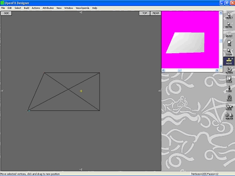
Then, with the move tool, move it to the left so it looks a little like this picture:


Once again make sure the tank is level by moving the vertices up or down.
Deselect and click in empty space. Now Insert a Sphere.


Make it smaller with the scale tool. See if it is the right size to lie on the tank by moving the GL viewer. Resize it so it looks like it is just the right size to fit on top of the tank. Then deselect all vertices. Then select only the bottom half of the sphere.

To make sure it’s selected, the vertices will turn yellow. The deselected ones are red. Now press Delete. Now only half of the Sphere is there.
Now select that half and drag it over the tank. Make sure it is close to the tank but not touching it. Use the scale tool if the picture is too big. Select all of the vertices (select>select all) to move as a whole or only select a part of the model to move as an individual part. When you think you got the sphere in the right location go to the top view. Re center or resize to fit on the tank. Then go back to the side view.

Deselect all and then click in empty space. Insert 1 cylinder, then click elsewhere and insert another.


Resize them with the scale tool to look like wheels.

Deselect all and then select one wheel. Set it about 2 inches under the tank and do the same with the other wheel.

With the vertices on both wheels selected go to the top view. If the model is off to the edge, use the pan tool to center it. Move the wheels off to the side so you don’t interfere with the other images.

Deselect, and re select only the vertices on the right side of the wheels.

Move the vertices to the right. Deselect, and do the same to the left vertices but this time moving left.

Move the vertices until they are about an inch away from the left side of the tank.


Now deselect, and select all the vertices on wheels to right of the tank. Move them in until they almost touch the tank.

Deselect and do the same to the left side. Remember to keep the wheels straight.

Notice the yellow cross that is the center. So select the whole model and move it there. Then re center the model with the pan tool. Now switch back to the side view and select all the vertices on both wheels. Move the wheels up into the tank so it looks like the wheels are attached to it. Go to Materials>Default Materials and select the color palettes. Change both to white if they are not already then close the menu. Go to Attributes>Material Settings.

Click on the color palette and select black or dark gray. Then go to the textures tab and click the color palette. Select the same color you chose first. Then go to the Maps tab and select Set. Click new and then and then click drop and then close. Your model so far should look like this in the GL Viewer on the right corner of the screen.


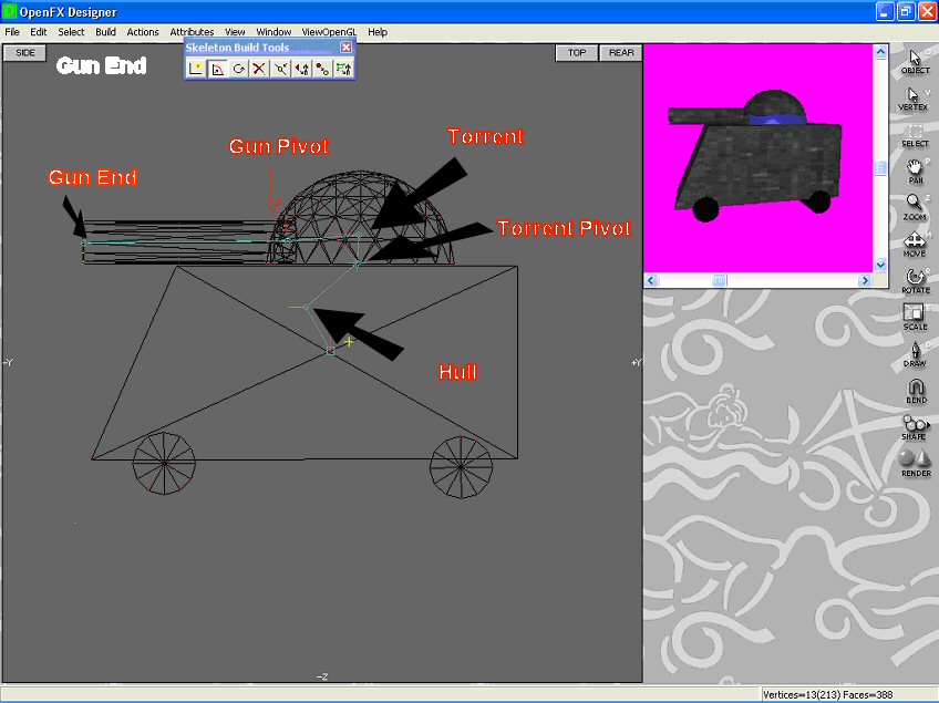
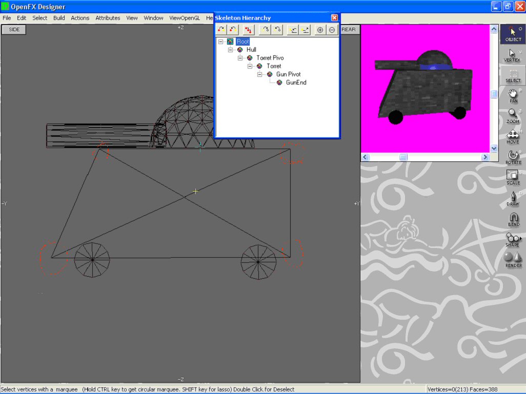
Now deselect all and click on an unused portion of the screen. Insert a Cylinder and re size it so that it is small enough, but no too small, to be where the tank shoots. Now go to top view and move it outside of the tank. Then rotate it to the left about 90 degrees using the Rotate tool. Deselect all, and select the front vertices of the recently worked on cylinder. Move those vertices about 4 inches towards the front of the tank.

Now select the whole thing and move it towards the tank. Attach it to the Dome.

Now go to the side view and move the Gun and attach it to the Dome.

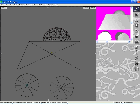
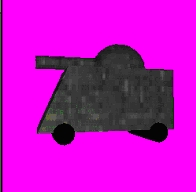
Make sure that the torrent is not touching the body of the tank itself. Next, select everything except the wheels. Make sure the vertices of the tank on the bottom are selected. Go to Attributes>Material Settings, click the Maps tab, click set, click new, click edit, check the surface box and find the Camouflage color, open it. Then close all the pop ups. Notice how the wheels changed colors. First deselect all, then reselect all the vertices for the wheels and then go to Attibutes>Material Setting. Click on the palette. Select the black color and. click On the Maps tab, click drop. Click done and the image immediately restores to black wheels. So far you image should look like this:


But that is not all. We are only 3/4ths done. Now deselect everything and select the bottom half of the dome.

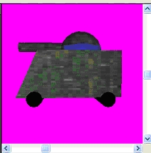
Now go to Attributes>Material Settings and click on the color pallette. Put in these values (red/green/blue) 199/255/255. Add to custom colors, select that color, and click OK. Now go to the Maps tab and click set, click Drop. Close all popups. Now deselect all and select the vertices at the end of the gun.

Now change the color to black or any color you desire, bearing in mind that the more variety of colors you add to the model the more arduous it will become in making a palette, and then go to the Maps tab and drop the current map.
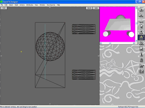
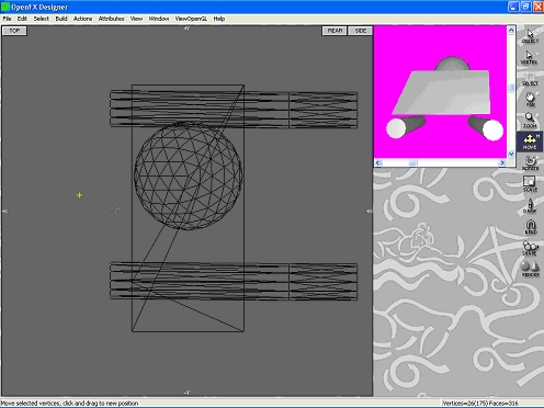
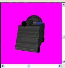
Your final product should look like this:
:Side View
:Front view
 
Now we have to apply a skeleton to the image to allow it to be animated. This allows the image to be animated. Deselect all. Go to Edit>Skeleton>Build Joints. You then see a box somewhere on your image. Click the second box on the Pop up to move the box on your image. Then click the yellow box and move it (the root Joint) to the middle of your image. Then click the Build joint button (1st box) and click and drag to where you want the next joint to be. Follow this Picture and name the joints accordingly.


Now close the Joints box and open up the Edit>Hierarchy Joints selection. Press ctrl+D to Deselect all vertices. Open up all the joints. Select Hull and then select all the vertices that you want to be the Hull. For the Hull, select the main body.


Be careful not to select anything but the main body. With Hull selected, click Attach (6th button). Then deselect all, click Turret, and select the dome and everything inside it.

Then Click Attach. Now deselect all and click GunEnd. Select the end of the Gun and Click attach.

Now Save your Model and we are done with designing. If you think that was hard, well this is even harder. Now for the animation. Now go to Window>Animator. This should take you to the animations. On the toolbars to the right, click insert>Robot

Search for your model and open it up. Go to Insert again, but this time insert 5 lights. The first one with normal settings, and the next 4 with No Shadow.

Once this is done, Insert ground and change both palettes to Magenta (r255/g0/b255).

Click OK. Now press “a” to bring up the select actor pop up (Edit>Select Actor). Select Camera. Now press “K” to bring up the Keyframes window (View>Show Keyframes) if it is not already there. On the bottom of the screen, a box that covers the whole bottom will pop up. In that box double click the blue box to position the Camera. Enter these settings: 17.68/-17.68/12 (X/Y/Z).

As you will see, you cannot see the camera any more. Don’t worry about it. We will fix it some other time. Now scroll down until you see “target (camera).” Double click the position box and enter 0/0/1. This tells the camera to focus at this spot. Then scroll until it says robot1. Double click the positioning box and enter the settings 0/0/1. This puts the model at the focus of the camera. Now scroll to the Ground object. Double click the blue box and enter the settings 0/0/0. Now scroll to Light1. Enter the following in the positioning box according to the settings X/Y/Z:
Light1: 0/-1/30
Light2: -15/-2/6,5
Light3: 0/-15/6,5
Light4: 15/-2/6,5
Light5: 0/15/6,5
Now delete all of the target lights by pressing ‘a’ (Edit>Select actor) and select one target light at a time. Then press the delete button and conform deletion. Do likewise with all the other targets.
Now we have positioned the lights, the camera, the ground, and the model. We have one more step until we get to the fun stuff. As you look in the top view, the camera and the lights are not visible. With the zoom tool, click the top view and zoom in by moving the mouse up until you can see the camera and lights. Zoom in by clicking and moving the mouse up, zoom out by moving the mouse down. If the objects are still out of view use the pan tool. Click and drag in all the views to make them look like this:

The model is pretty small isn’t it? Using the scale tool, press ‘a’, and select Robot1. Click the image and enlarge by moving the mouse to get the image to look like this:

Exit the scale tool and Open up the positioning box for the Robot1. Enter the settings [0/0/3.97]. Now the image should look like this:

If it doesn’t, make sure that your model is selected, by pressing ‘a’ and selecting Robot1. Then just move the model to your liking by using the move tool and clicking on the model on any of the three viewing screens then moving it. Next set the Animation length to 80 frames by going to Frames>Animation Length. Now select the Camera actor. Press anywhere on the positioning row (teal line). Click yes to split the channel. Now click on the newly created box and hold your mouse button and move the box to were you want the keyframe to be. By following the same procedure make the keyframe window look like this:


The boxes are at Keyframes: 9,10,19,20,29,30,39,40,49,50,59,60,61,69,70,71,72,80
Now scroll down to the Robot1 Keyframe and do the same procedure but with the green line:

The boxes should be at: 1,5,10,14,19,20,24,29,30,34,39,40,44,49,50,54,59,60,64,69,70,75,80
Now we are ready for the animation part. Go back up to ‘Camera.’ Double click on the box for frame 10, (3rd box) and put in the following settings: 0/-25/12. Do the same for frame 19. Follow these steps and put in the following settings for all of the frames:
On all the keyframe, make sure the tween characteristic is filled in, not Spline Tween. Spline tween will make the camera zoom in and out randomly between each keyframe.
X/Y/Z
Frame10,19= 0/-25/12
Frame20,29= -17.68/-17.68/12
Frame30,39= -25/0/12
Frame40,49= -17.68/17.68/12
Frame50,59= 0/25/12
Frame60,69= 17.68/17.68/12
Frame70-80= -25/0/12
Now it’s time for the animation. Slide the slider on the OpenGL viewer to frame 4. Select Robot1 by pressing ‘a’ and selecting robot1. Next press ‘V’ to bring up the robot Hierarchy popup. If it does not work, make sure that the vertex actor is not selected; select the actor tool then press ‘V’. Look at the Hierarchy Robot1 popup. Open up all the Parents.
 
You will see that there are seven boxes, all have some kind of motion on them. They all can be used to move your joint in different directions. Now select Torret and then click the box with a ‘Z’ on it. Now click and hold on the outside of the screen and move the mouse according to where you want the torrent to be when it hits frame number 5. Once you have done it, close the popup. Now slide the slider back to the 1st frame. Hold it and slide it slowly to frame ten. The tank’s torrent should to one side and then back again. Now do the same steps, but with every frame that has a 4 in the last digit. The exception to this is fr75, make sure you do that one the same way. Well, I’m sad to say that our Animation is over L. Now all we have to do is render it. Click Render from the toolbar off to the right. A big popup will then show up

Under image file format select ‘Animation’. Type ‘TankFidget’ for the movie name and ‘tank’ for the image name. You can also specify which directory to place your animation in and your image in. Since the animation is a tank, select ‘Specified’ under the change preset tool. Make the size 100 width x 75 length. Then select ‘A range of frames’ at the bottom of the pop up. Last step in Animation; render the file as a gif. Then select Render, and we are done if you just want to animate your unit. If you want to import your unit into Civilization keep reading we are only half way done. Skip down to the next page…..


To start the importing tutorial, I want to congratulate you for coming this far. Now open up PSP (Paint Shop Pro 8), FLICster, and Animation Shop. Open up your tank in Animation Shop. Next go to FLICster and open a new document.

Change the frame size to 100x75

Change the frame count to 10 Frames. Change the frame delay to the highest possible and change the Base File Name to TankFidget. The last step is to change the output Directory to ummmm, well, to the directory you want it to be exported into. Once this is all done click export and select yes to open up the newly created FXM file. Now open up PSP and open the new FXM file. GO to Image>Palette>Save Palette and save it as ‘original.’

Make sure you specify the destination of the palette and save it as a [.pal]. Now go back to Animation Shop and copy the first frame. Paste it as a new image in PSP. Now go to Image>Decrease Color Depth>Decrease to 256 colors. Answer OK on all the prompts. Go to Image>Palette>Edit Palette. Then highlight the first color as seen in this picture:

Now draw columns and rows on a separate sheet of paper like below: (if you use graph paper you wouldn’t have to do this.)

R G B


R is for red
G is for Green
B is for Blue


Here comes the labor-intensive part. You have to write the coordinates of each color in those slots.
Ex. 121/255/46
Copy every single non-magenta color(anything close to 255/0/255 is .
Now make a separate sheet labeled ‘shadows-last two rows’


R G B


This table is only for the off magenta colors.
Hey, I know this requires a lot of patience, but if I can do it, you can too.
Once you are done copying the palette, edit the palette on the fxm storyboard (the one you just pasted the first slide on). The empty square immediately following the first 4 rows is where you will begin entering the coordinates of the colors you copied. Double click on that square and enter the coordinates of the first color you copied. Work your way to the right until you don’t have enough room. Continue one row lower to the left. Now delete all the magenta colors except for the ones in the last row. Once that is all done skip to the last row. Make sure that you don’t delete the last two colors; the last is magenta, and the second to last is the border. On the third to last square enter the copied colors starting from the one you copied on the Shadow Page. Work your way to the left until you’re out of room, then go up a row and start again at the rightmost square. Go back up and set the first 4 rows to lime green (a color you don’t use). Then take the blueish colors, ones by the neck of the tank, copy them, and input them in the 4 rows starting from the first box. When you are all done, click OK, and save your palette as {Tank.pal}. Now the easy part comes in. Close that image and open up the 100x75 frames you saved in FLICster. Now load the saved palette by going to Image>Palette>Load and select your [Tank.Pal]. Switch to AS (Animation Shop) and copy the first frame. Go back to PSP and click on the storyboard to select it and press ctrl+E to paste as a selection. Paste it in the first square.

Make sure that you don’t jump the border.J Now go back to AS and copy the 2nd frame. Go back to PSP and press ctrl+E. Paste it in the next square. When you are done with ninth one, paste it again on the tenth frame. Only do this on the first row. Now go to AS and copy the next Frame, and paste it in the next row, first box. Continue in these steps making sure that you don’t cross the border. Save in between so you don’t loose your work! Once you are done cutting and pasting, select the selection tool on the toolbar to the left. Copy a magenta piece and paste it onto the top of the square. Be careful not to paste it over the border. Your final image should look similar to this. Now when you make the other animations, use the same palette you made.*

Save your work and go back to FLICster. Go to the export tab and export the animation into the original Directory (just erase the word ‘FLICster’). Well, after a long Tutorial, we are done. Congratulations, you just Designed and animated your first Civ unit. To get the default view, and all the other views, I’ll leave that up to you to do.


EDIT: This is the hard way of making a palette. I just found a new way, much easier(I praise the creators of this new utility). It’s called Pedit. I will have a separate tutorial on how to use Pedit with this same model depending on the demand of it so VOTE.


CREDITS


Thanks to the Morpheus for putting on his tutorial on Openfx
Thanks to the Firaxins
Thanks to Muffins for posting his tutorial on skeletons
Others who I mistakenly left out


Look for my next tutorial, PART 2 coming soon.
Please VOTE in the poll so I can have a better idea on what to clarify, delete, add, and whatnot.
 
I want to attach my tutorial file. DO i go to "Manage Attachments" also. I did that, Attached my .zip file and waited for the bar to fill on the bottom of the screen. Do have an idea of how long io should wait once its full.
 
It shouldn't take long (depend on the size of the file you're uploading) and the pop-up window should also change to show what files are currently attached to your post.

The file size limit for attachments is 500k. Anything over that (and still under 3MB) should be uploaded via the upload link at the bottom of the page and a link to the file put in your post.
 
Thanks muffins, the file was more than 4mb
 
Still doesnt work. I split the file into 2. They both ended up to be 2mb in size. I tried to upload the first one first by clicking the click on the bottom of the page. I then browsed for my file and clicked upload on the popup. The bar on the bottom of the popup filled up but then nothing happened. Can someone please review step by step on how to upload a file. Thanks
 
Uploading a 2MB file, even on broadband, takes time. On a normal modem it can take 5-10 minutes.

Ignore the progress bar in the pop-up window because it's always wrong. When the file is uploaded the pop-up window will change and you will see a link allowing you to view the uploads folder to confirm whether or not your file uploaded ok
 
Thanks Muffins :smile:
 
You wanna know how to attach images? well upload the images to the server and then after that put the image tags around the direct link to the image file like this

[ IMG ]http://www.yourimagefile.com[ /IMG ]

Put it like that but without the spaces in between [ IMG ] but basically should look like this
 
I was reading your tutorial and everything seemed to be going fine, until i came to the animating part. After setting up all the lights and everythung, i actually tried to animate the example tank i had made, and found that when i tried to rotate the turret that the entire tank (except the wheels) rotated instead. This is then tried with all the other joints, to the same effect. Im sure i followed your explanation of the joint, and building the joints and their heirarchy to the letter, and im struggling to see what i have done wrong. Please enlighten me...

RESPONSE:

1. In the designer, make sure that when you select the joint in the joint heirarchy window only selct the vertices that you want to associated with that joint. Everything else should be deselected.
2. Then click "Attach"
NOw your selected vertices should should be attached to the selected joint
 
polyphemus said:
Change the frame count to 10 Frames. Change the frame delay to the highest possible and change the Base File Name to TankFidget. The last step is to change the output Directory to ummmm, well, to the directory you want it to be exported into. Once this is all done click export and select yes to open up the newly created FXM file. Now open up PSP and open the new FXM file. GO to Image>Palette>Save Palette and save it as ‘original.’

Make sure you specify the destination of the palette and save it as a [.pal]. Now go back to Animation Shop and copy the first frame. Paste it as a new image in PSP. Now go to Image>Decrease Color Depth>Decrease to 256 colors. Answer OK on all the prompts. Go to Image>Palette>Edit Palette. Then highlight the first color as seen in this picture:


Your tutorial rocks. Thanx for making this! I got up to here but when I tried to do this I realized that Paint Shop Pro doesn't support FXM files.

I made the animation, rendered the whole thing in GIF Then I followed th FLICster instructions but when I click export in FLICster I don't get any dialogue, or any think to push yes on. FLICster just shows the new animation, which is unfortunately totally blank.

Then I go to PSP and try to open it and it reads: "File type not supported."

What did I do wrong???

:confused: :confused: :cry: HELP!!!! I want to make a unit! PLEASE!!
 
1. Sorry for not adding this in...FLICster should have alos created a pcx file with the same name as the FXM. These two files are linked to eachother. The FXM file is read by FLICster and the pcx is read by PSP.

2. When you export a newly created storyboard, a pop-up should display saying "open new FXM file" with the options of yes or no. Hit yes and go to the animation tab. The animation should be blank. This is where the old copy and paste method takes place. But recently i've found a utility called SSB and PEDIT visit those threads for help on those programs. SSB creates the storyboard for you from individual BMP's. PEdit creates the pallette for you.
inside PEdit you can open up an image and select all the necessary colors. However, you need to arrange the colors a certain way.

The above picture is the layout of the pallette. The first five rows are the the changing CIV specific colors. The first one is the one that is used. The colors need to be arranged fom brightest to darkest.
The magenta color (last color) is the transparency in game.
Lime green is the shadow
Blue is the haze colors. I didnot have any anti-alias colors so i chose a color that wasnot in the animation.
The second to last color, also blue is the border in the storyboard.

Indepth analyses:
FIrst row.......CIV color
rows 2-5 unused CIV color
6-14 are the colors used to animate the unit
row 15=haze colors
last row=shadow colors
second to last color=boarder color
last color=transparency in game color

This is the unit i used for that palette:


The yellow is the in game CIV color
 
just glad i could help
 
Top Bottom