Designing the Time Machine

Blue Monkey

Archon Without Portfolio
Joined
Jul 31, 2005
Messages
11,325
Location
Timeless Isle
After discussion by the core team, here’s the public start of the design process for the “space race” victory. It’s going to be the invention of a time machine. The first posts are what I have discovered about the possibilities based on a comparison of the standard Firaxis screen & versions in a few different mods.
I apologize in advance to anyone with a slow connection. I have reduced the images. But I chose not to take them down to thumbnails because I feel it is critical to the discussion to be able to readily compare the images.

What We Know & What We Can Deduce

Spoiler :


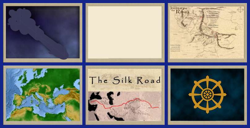
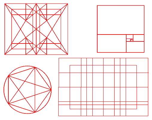
Above is a comparison of the backgrounds from Firaxis, a blank, Lord of the Mods, Rise & Fall of the Roman Empire, The Ancient Mediterranean, and The East Asia mods. Shows that there’s a lot of freedom in the background that can be used. RFRE & LOTM, & EA have a screen in the art folder, but the victory is not enabled in the mod itself.

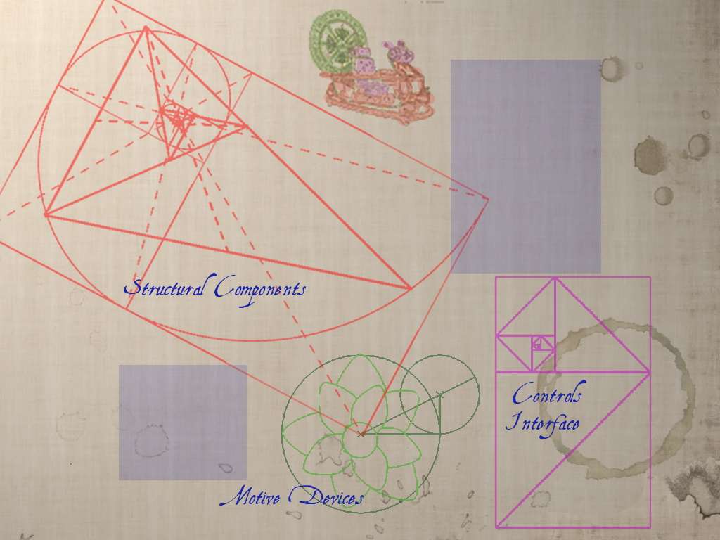
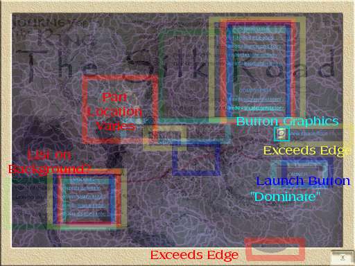
Next I took screen shots in-game. Each shot was taken the same as the Firaxis - with the last component clicked & shown in-situ. Then I did an overlay with relevant elements boxed in identifying colors from each of the following mods:
Red - Firaxis
Yellow - Alexander’s Conquests
Blue - The Ancient Mediterranean
Lt. Blue - Warhammer
Green - Lord of the Mods​

Spoiler :

What I learned:
  • The beige border need not be the boundary - both Firaxis & Alexander’s Conquests have elements that extend into the frame.
  • The “view” button graphic varies
  • The “launch” button graphic is not used by Warhammer - it is clicking on the text that initiates the action anyway
  • Associated text can be changed - evidenced by Warhammer’s use of “Dominate” rather than “Launch”
  • The location of the component varies - confirmed by looking at the component graphic itself. The component is isolated on a magenta graphic the same size as the screen background.
  • LOTM has a list with variant wording on the background. This seems not to be functional because:
  • The parts lists appear in identical locations on every implemented screen
  • There is no variation from the blue color of the list text used by Firaxis
I sum up what this means in terms of guidelines for our design at the beginning of the next post. If anyone has practical experience with something functioning differently than I understand it please jump in.
 
Guidelines for Screen Design
  • We have freedom to use the whole screen - borders not needed
  • We can use any background image we like
  • We can change the button graphics - even eliminate them
  • We can change the text
  • We can change the parts positions from what Firaxis used
  • We cannot change the location or color of the texts
In the private discussion we came to the temporary thesis that the race is about inventing the time machine rather than building & taking off in it. Thus the screen will represent a drawing or blueprint in development. There are several types of possible backstory of the designer - Scots Engineer, Gentleman Tinkerer, Crank Scientist, Isolated Inventor, Misanthropic Mastermind, Lady of Independence, etc. The screen composition would vary, depending what kind of character we wish to portray.


A Design Possibility
Here is one possible interpretation - just a “quick and dirty” mock-up:

Spoiler :


The unmovable text is incorporated into the overall impression by being made part of diaries or lab notebooks. The working drawing (where the parts will appear) is from a design sketch of Babbage’s analytical engine.

I like having little in-jokes, there are few here. The pocket watch is reversed & has a key. There is a scribbled reminder of an important date, of significance also in understanding relative chronometry. The launch is via a tool from a certain doctor’s kit. Finally, there is a list - which assumes that the inventor is the protagonist of Wells’ story - of potential dinner guests. With one exception, all have some activity in common:
Jack
Van Stopp
Cavor
Nebogipfel ?
Sindulfo Garcia
Señora Mendoza
A. Rhoodie
Ashbless ?​

Some potential design elements are laid out in the next post.
 
Potential Elements of the Suggested Design

The following are meant to be suggestive only. I'm sure between all of us the available variations are innumerable.

The blotter itself was adopted from a graphic at steampunkwallpapers.com. There are quite a few usable choices there. The folded parchment is from a museum site.

Spoiler :


I imagine the various parts as looking drawn - they can be letter keyed to the list text - the list letters can even be part of the background. Another way to do the list would be as a table on the blue print itself. Here are some visual idea sparkers:

Spoiler :


The whole screen could be just a blueprint. Personally, I favor having it in a context, letting us use some Dupinisms to tell our backstory. The desktop could be as bare or as cluttered as we like. Besides the obvious, such as watches or other devices, we can have our little jokes in many ways. Is that paperweight a reminder of a breakthrough moment or a tragic past? What photograph or other image inspires our inventor? IMHO Verne is a little obvious. I was thinking, for example, of a sepia-toned, blurry “Persistence of Memory”. I’ve got access to quite few large images of period book covers, and many many typefaces at my disposal, so our inventor can have at hand any reference wished.

Spoiler :


So where do we go from here?
 
The fundamental design is constrained by the hard coded elements. The basic “look & feel” desired will determine the rest.
Does the desktop + blueprint idea look like a winner?

Assuming it is -
  • There’s a lot of freedom in picking & arranging the parts themselves. We can brainstorm by putting up images of anything that looks bizarre, intriguing, fun, or just cool. In the end the choice ones will get converted to “drawn” outlines.
  • Once we've got a background the individual parts can be rearranged repeatedly on a multilayered graphic (like a GIMP image). Once we like the composition they can be connected by conduits, wires, gearing, etc.
  • There is the decision about how to encorporate the hard-coded lists: books, loose papers, or charts on the blueprint are just three possibilities.
  • Finally, what other decorative elements do we want to include?

Gentlemen, & Ladies, the floor is open for discussion.

:coffee:
 
How about a picture of the (sp) antikathera mechanism... found at the bottom or the sea but unknown purpose?... Maybe it went back in time only to exist until now.
 
Looks interesting!

For my Industrial Espionage scenario, I was going to have the SS being the designing and marketing of a new product, which is quite similar to what you have, so it'll be interesting seeing what you come up with, too :)
 
Here's a link to a page with some design elements:

http://colemanzone.com/Time_Machine_Project/dw_machine_concept.htm

Given our slavish devotion to 19th century literature in this mod, we want to seriously consider that whatever we end up with, it would be in our interest that the end result seriously echoes the Wells time machine in it's design.

Wells describes:

Spoiler :
a glittering metallic framework

There was ivory in it, and some transparent crystalline substance

it looks singularly askew, and that there is an odd twinkling appearance about this bar, as though it was in some way unreal

'Also, here is one little white lever, and here is another.'

this lever, being pressed over, sends the machine gliding into the future, and this other reverses the motion. This saddle represents the seat of a time traveller.

Parts were of nickel, parts of ivory, parts had certainly been filed or sawn out of rock crystal

he twisted crystalline bars lay unfinished upon the bench beside some sheets of drawings, and I took one up for a better look at it. Quartz it seemed to be.

one of the ivory bars is cracked, and a brass rail bent

one of the nickel bars was exactly one inch too short

tried all the screws again, put one more drop of oil on the quartz rod, and sat myself in the saddle

the starting lever in one hand and the stopping one in the other

The little hands upon the dials that registered my speed raced round faster and faster

reaching over the bars of the machine I unscrewed the little levers that would set it in motion, and put these in my pocket

One dial records days, and another thousands of days, another millions of days, and another thousands of millions.

the thousands hand was sweeping round as fast as the seconds hand of a watch

There in the flickering light of the lamp was the machine sure enough, squat, ugly, and askew; a thing of brass, ebony, ivory, and translucent glimmering quartz


Nowhere in this description do I find the movie machine; there are no spinning wheels or moving parts anywhere in this description, save for the levers and hands of the dials. I'll admit, however, that the movie machine was more impressive in both its incarnations.

As for the buttons, etc, I found the following in the labels.txt file:

MODULES
COMPONENTS
STRUCTURAL
Needs
ENGAGE
Exit
COMPLETE
assign
No city may build
Cities
items
item
Queue slot
SS


There may be more...

I can imagine all sorts of "inside" time machine things to add: a part called 'Flux Capacitor' (you have to have one, I insist); a module called Wabac - the name of Mr. Peabody's time machine in 'Rocky & Bullwinkle'; The name 'Chronic Argo' from H.G. Wells' first time travel story; the number '42' written scribbled on the scratch pad; A 'briode nebuliser' from Dr. Who, etc.,etc.

But I should also say that I'd be in favor of keeping the focus on the diagram itself; too much extranea will muddy the effect you're aiming for. I would keep the bottom right 'launch' click point fairly easy to find: I had the painful experience of being unable to find "launch" once in a game, and at that late stage, it's devastating. We can start thinking of synonyms: "Build", "Approve", "Send". In any case, someday someone could design a little move for us in which the diagram lifts from the page and becomes a real machine! Small differences in scale aren't particularly noticed; perhaps the notebooks could shrink a bit to make more room for the design.

Overall, I think you're on exactly the right track, and I'll be fascinated to see what you do with it.
 
That is a gold mine!
whatever we end up with, it would be in our interest that the end result seriously echoes the Wells time machine in it's design.
... there are no spinning wheels or moving parts anywhere in this description, save for the levers and hands of the dials.
Agreed that it definitely needs the Wells/Vernian style. But an "engine" rather than a device. Certainly, crystals; also a little steam or at least pneumatics for the controls. & something to connect the dials to the engines.
As for the buttons, etc, I found the following in the labels.txt file:

MODULES
COMPONENTS
STRUCTURAL
Needs
ENGAGE
Exit
COMPLETE
assign
No city may build
Cities
items
item
Queue slot
SS


There may be more...
... We can start thinking of synonyms: "Build", "Approve", "Send".
I'd leave changing these until we have the machine design roughed out. Then the changes we make will suit the visuals.
I can imagine all sorts of "inside" time machine things to add: a part called 'Flux Capacitor' (you have to have one, I insist); a module called Wabac - the name of Mr. Peabody's time machine in 'Rocky & Bullwinkle'; The name 'Chronic Argo' from H.G. Wells' first time travel story; the number '42' written scribbled on the scratch pad; A 'briode nebuliser' from Dr. Who, etc.,etc.
We have 10 parts to design. The positions on the list & therefore the divisions of the TM are hardcoded: 4 "modules", 4 "structural", & 2 "components". We can rename them but not shift the number of pieces from one section to another afaik. Off the top of my head I'd suggest 4 pieces for the actual engine, 4 to the control panel (levers, time dials, some kind of engine monitoring dials/controls, and a fourth?), with the last two being the seat & frame/chassis. If that sounds about right then we can set up a chart (1st post?) with columns something like "label letter", "assembly [1 of 3 categories]", "part name", "description (Wells' items)". We can start off with a lot of blanks, but at least it will give us something to keep the discussion organized. When everyone starts finding cool junk we know how to talk about it. Further down the road identified and assigned image thumbnails can be added.
But I should also say that I'd be in favor of keeping the focus on the diagram itself; too much extranea will muddy the effect you're aiming for.... Small differences in scale aren't particularly noticed; perhaps the notebooks could shrink a bit to make more room for the design.
The whole screen can be the blueprint. The menus/buttons can be charts on that blueprint. I think the overall look of the blueprint should be separate diagrams of the three assemblies, with a small sketch on the background layer of what the overall machine will look like. That way we've got more wiggle room as far as making the parts of each assembly fit together. I'll try to get a visual together to explain what I mean later, but for now how's this for a blueprint background?
thumbnail


The scribbled notes can be here or there, but the OT ones can be in a smaller, diary styled book. All the extras can be added in once we've got the key design elements in place. The image I posted wasn't meant to be an actual design. just some concept art.

So these are the tasks I see to be done at this point:
  • Settle on the three main assembly divisions
  • Rough out descriptions/names for the components of each
  • Decide in very broad terms what the blueprint should look like
  • Start finding cool visual components to suit the list
 
So, if I follow your post, what we have so far (if we use the elements provided us by Mr. Wells in The Time Machine) is:

4 modules:
- Dial Array (incl. 2 screw-on pocket-sized levers)
-
-
-

4 structurals:

- Quartz rods (oiled)
- Nickel rods
-
-

2 components:
- Operator's seat
- Brass Frame

I've been doing some research to try to determine how Wells believed his machine worked, and I've come up with the following:

The Quartz rods are the power source, by a process called Piezoelectricity, first demonstrated in 1880 by Pierre and Jacques Curie (yes, Pierre was Marie's husband). The clue he gives is that the small model in Chap 1 is compared to "a small clock".

The nickel rods, as far as I can determine, are actuators and, properly arrayed and filled with magnetic material, could produce a magnetic field that vibrates at a rate controlled by the natural vibration of the Quartz rods. Interesting thing about the nickel bars - in Back to the Future, Doc Brown says that the stainless steel skin of the DeLorean is for "flux dispersal". Well, the primary component of stainless steel is nickel.

Wells traveller spends much of the first chapter discussing time travel in terms of geometry. At one point he talks of "four dimensional geometry". He might have been thinking of a lecture by the brilliant Bernhard Riemann, who in 1854, revealed Riemannan Geometry, which allows the plotting of vectors in curved space-time.

For to travel in time, but not in space, the traveller reasoned, we had only to set a vector (a right angle to reality) along the time-line and follow it. 'Why should he not hope that ultimately he may be able to stop or accelerate his drift along the Time-Dimension, or even turn about and travel the other way?' he says.

This is how Wells neatly goes around those who argue that one couldn't travel in time because the earth spins on its axis, which spins around the sun, etc. His traveller takes pains not to move in space at all, save to 'turn into' the time-current on his machine, which, thanks to it's fluctuating magnetic field, uses the principle of parellel transport along a line on a manifold (a portion of curved space), rather than striking off on its own into the great void. Though he couldn't have known it, he was describing something known in physics as Minkowski Space.

Now here's the part that'll bake your noodle: how do we know that we're on the right track? Wells inadvertently gives us a detail that allows us to reverse engineer the whole thing. When he first engages his time machine, he has the sense that he isn't moving at all, save a small thud as he starts (perhaps the same as one would feel as a rowboat slipped into a stream). Later, after he's picked up speed, however, 'There is a feeling exactly like that one has upon a switchback—of a helpless headlong motion!' What he's experiencing is called a Lorenz Transformation. This is what happens to someone who attempts to travel a straight line along a manifold in space-time:

Lorentz_transform_of_world_line.gif

Views of spacetime along the world line of a rapidly accelerating observer moving in a 1-dimensional (straight line) "universe". The vertical direction indicates time, while the horizontal indicates distance, the dashed line is the spacetime trajectory ("world line") of the observer.

Now, there are only three ways in which Wells might have known about the Lorenz transformation. He could have a) made acquaintance with Sir Joseph Larmor, a mathemetician at Cambridge who described the phenomenon in a paper published in 1897 - two years after Wells' story was first published; or b) in a case of extreme coincidence, he described a time travel phenomenon that hadn't been described yet, even in advanced physics; or (my favorite) 3) he did it himself, or knew someone who had done it.

Anyway, I've been three days at this on the theory that if we understand the function of the parts, we might be able to visualize them better. It certainly suggests that the quartz bars are set as smaller ones might be set in a watch
although why they're oiled in the story remains a mystery - perhaps it helps to achieve the proper vibrato.

It would also follow that the nickel bars would be along the sides of the machine, so to pull it to 90 degrees T. The ebony and ivory described in the story would be used in this context as ceramics are used in modern electronics, and for trim (although he might have a practical reason to make the lever handles of ivory - to avoid electrocution).

I could also imagine a babbage calculator onboard, tuning forks, and whatever it might take to maintain and steer a magnetic field. BTW, while imagining this, I also came up with an explanation of the flux capacitor: E. Brown was a nuclear physicist; he preferred to harness his power source to create a temporal speedboat that punched across the manifold rather than travelled around it. The Flux capacitor provides the temporal brakes, enabling one to do point-to-point travel rather than sliding to a gradual stop.

Feel free to use or discard any musings contained herein.
 
I'm glad you mentioned the Babbage connection - a smaller version for on-board calculations would explain part of the "small clock" reference. Here are some possible names based on your research:
  1. Quartz Rods = "Flux Capacitors"
  2. Nickel Rods = "Minkowski Harmonizers"
  3. Babbage Calculator = "Riemann Analyzer"
  4. The quartz rods insert into a = "Larmoral Transformer" = clockwork. The oil is to lubricate the mechanism. Finely-machined (and thus precise) watches use pine oil for example.
  5. Separate the dials & the levers = "Tachysmic Indicators" & "Diolkos Rack"
  6. "Clio-Tourbillon" could be the shield shown in the various movie models.

This would make the list look like

Modules.........Controls
Dial Array.......Tachysmic Indicators
Levers...........Diolkos Rack
Calculator.......Riemann Analyzer
???................???

Structurals ....Motive Devices
quartz rods.....Flux Capacitors
nickel rods......Minkowski Harmonizers
clockwork.......Larmoral Transformer
parab. shield...Clio-Tourbillon

Components...???
Seat..............Cockpit
Frame............Taffrail


Of course all of that is subject to change.


A word on some of the nomenclature -
  • Tachy- and Clio- refer to the measurement and control of chronology.
  • Diolkos is an Ancient Greek equivalent of a switching yard which was used for naval vessels. Rack refers both to a type of railway that works like a ratchet to restrict motion to the desired direction & also as an oblique reference to the stopknobs on a pipe organ. Controls the flow of time. The Greek reference is also a tip of the hat to the Antikythera mechanism.
  • Tourbillon is an element in a timepiece that "counters the effects of gravity by mounting the escapement and balance wheel in a rotating cage". So a clio-tourbillon would do the same for the problems navigating the spacetime manifold.
  • Cockpit - today we think of it in terms of airplanes, but originally it referred to the coxswain's station on a ship - where the rudders and other controls are dealt with.
  • Taffrail goes with the cockpit. The cockpit was in the stern. And the Taffrail is the outermost railing on the stern, which was often highly decorated. I don't know, it makes sense to me that a literate chrononaut might thus associate himself with men such as Sir Francis Drake who sailed into the unknown for Queen and Country.
So while all of these terms seem obscure they might in fact have made sense to a steampunk Victorian.
 
How about this variation on your theme:

Modules.........Motive Devices
quartz rods.....Piezo-electric Array
Computer.......Babbage Analyzer
clockwork.......Chrono-syncronization assembly
Flux Capacitor...Flux Capacitor

Structural Components
Frame............Taffrail
Dial Array.......Tachysmic Indicators
nickel rods......Larmoral Actuators
Ebony Plates...Structural Stabilizers

Interface Components
Seat..............Cockpit
Levers...........Diolkos Rack


Another thought I had was that a nineteenth century scientist might base the dimensions of the frame on the Golden Ratio, perhaps incorporating a Golden Spiral in the design.
 
Looks like our list is complete. I would like to include a Whovian name if possible.

I've collected images of golden ratio triangles, squares, rectangles, circles, spirals, pentagons, hexagons, regular solids, ... which can be used as temporary backgrounds for all the pieces. There's an interesting one based on petals of a flower that I think can be adapted as the basis of a gear assembly. I may be able to use it for the overall design of the screen as well, if it will work with the hard coded lists.

I think the overall look of the blueprint should be separate diagrams of the three assemblies, with a small sketch on the background layer of what the overall machine will look like. That way we've got more wiggle room as far as making the parts of each assembly fit together.
I hope to have this posted by Monday (busy weekend).
 
I think the overall look of the blueprint should be separate diagrams of the three assemblies, with a small sketch on the background layer of what the overall machine will look like. That way we've got more wiggle room as far as making the parts of each assembly fit together.
Here's the kind of thing I've been talking about:


Shown half-scale. Obviously the particular drawings are just a quick mock-up - not in any way a representation of the actual pieces.

The reddish parts are to suggest what it could look like when a certain part is selected from the list. Probably they would not be red in actual play. It looks to me like the game shows a faded version of whatever "needed" part is selected. So the drawing would end up looking dark in the completed areas and lighter in the "needed" selection, with everything else still blank.

Since the game simply uses a full screen graphic for each part, with the rest of the image magenta, afaik we can have pieces of the graphic at different places on the screen. I'd like to put that to use by having a small sketch of the full machine to show where the selected part would fit in the overall design.

:coffee:
 
An impressive study of the space race screen. Blue Monkey, I'd suggest taking post 1 and the guidelines from post 2 and setting up another thread in the Tutorials subforum...for those of us CFCers that don't compulsively read nearly every thread started...I think many would find it very useful, particularly the comparisons, lessons learned, and excellent graphical representations of it all.

As to the steampunky thoughts...I don't have much to contribute as to the content, knowing little more about steampunk than what I gleaned from watching the League of Extraordinary Gentlemen and Wild Wild West, though I am very intrigued by all of the indepth work going on here. Intrigued enough to be looking forward to toying around with the mod when it comes time. But I dither. I very much like the most recent mockup by BM and think the faded/coffee stained look is excellent. The red highlighting also seems effective. I hope you bring the notebooks back in when you add the parts lists--that seemed a novel and eye-catching way to do that. I think I would stray away from the Vitruvian Man and keep to mechanical-like sketches and notes...that's as close as I'll come to semi-informed criticism.

All in all, beautiful work, well thought through and artfully envisioned! I look forward to seeing more!
 
Glad to see you checking in here Micaelus; your contribution to the conversation is always constructive. Don't forget to check out our Unit Requests Thread (which needs a bump) for an opportunity to contribute in a major way. Or just hang out and kibbitz - you're welcome either way!

PS - I'm thinking, BM, that it might be a good idea to move that thread over to our little subforum....
 
After a lot of contemplation, here's my latest conception of the layout.
thumbnail


The blue blocks are the areas reserved to firaxis text & buttons. Red - the components themselves need not be triangular, but the angular relations between them will. Green (mostly circular components) - I found a flower schematic in which the petal sizes proceed by the Fibonacci sequence. That can be a basis for a gear-like meshing of the components. Purple - the cockpit & levers seem to me to be pretty rectilinear already.

All these colored bits are just guidelines to where the actual components will be laid out & will not appear in the final. Riffing off Balthasar's mention of the golden ratio I've made each sub-assembly a version of the same. The whole Time Machine will thus embody the maths of chronautics. I have some other premade layouts available if what I've proposed misses the mark:
thumbnail


Now I just need some volunteers to rummage through the Steampunk Pick-a-Part yards. Link me to images of weird machinery & device parts, in other words. Check Balthasar's list above for inspiration.

:coffee:
 
This site has great images of the 'original' Time Machine as seen in the movie being restored.
http://www.geocities.com/timemachine_nz/restoration.html?20097
It also has a collection of images from the 2002 remake of the movie.

I did a random troll of Google images too and here's what tickled my fancy. Not all are on the list but I include them anyway for inspiration if nothing else.

"Ignition" Key
http://cryoflesh.com/shop/images/Steampunk Laboratory Chaterlaine Necklace.jpg

or this 'crystal tipped' one: http://www.jlhjewelry.com/wp-content/uploads/2009/06/jlh-609-timekey.jpg

Cockpit (Barber Chair)
http://www.geocities.com/timemachine_nz/images/3d_berninghaus_01.jpg

http://www.geocities.com/timemachine_nz/images/3d_berninghaus_02.jpg

Random Dials
http://weburbanist.com/wp-content/uploads/2008/11/steampunk_3_main.jpg

Control Panel?
http://weburbanist.com/wp-content/uploads/2008/11/steampunk_3_1a.jpg

Fluid in pressurised canister doing something vitally important, I just don't know what.
http://images.google.co.uk/imgres?i...+laboratory&gbv=2&ndsp=18&hl=en&sa=N&start=36

Random Components
http://www.instablogsimages.com/images/2008/02/28/ssteampunk-time-machine_54.jpg

http://www.instablogsimages.com/images/2009/02/26/steampunk-slimline-mobile-phone-054_PqGOt_3858.jpg

Time Machine Self Assembly Instructions
http://www.moviemachinenews.com/wp-content/uploads/2008/04/080410_timemachine1.jpg

Scale Model
http://johnthenewsking.files.wordpress.com/2008/04/time-machine4web.jpg

Time Machine Engine?
http://farm4.static.flickr.com/3249/2769471159_e51c6eb305.jpg?v=0

Joke Items

Goggles (what every steampunk time traveller should be wearing to protect them from flashing lights ;))
http://corvusart.com/blog/wp-
content/uploads/2008/10/steampunk-goggles.jpg

Steampunk Sonic Screwdriver ;) You did mention a Whovian element was needed.
http://gadgets.boingboing.net/assets_c/2009/06/DSC07289-thumb-620x465-22759.jpg

Steampunk USB stick - for the desk of the inventor -thank goodness he back everything up ;)
http://zedomax.com/blog/wp-content/uploads/2009/06/steampunk-usb.jpg

Crystal and Brass Lever - for the Time Machine's Flushing Toilet
http://www.capecodbrass.com/baldwin/2008/5845.RP.jpg
 
It's been an interesting evening. One of the local cable channels got stuck on a photo of the Hindenburg crashing in mid-crash, so that's been on the TV for a couple of hours. I've been listening to King Crimson & Loreena McKennitt and browsing Tesla drawings. I think he invented most of what you need:

Tesla drawing from Patent for Turbine: that big spinning disk on the back of the machine.

Spoiler :


Another tesla drawing: Conversion of steam power to electricity
Spoiler :


A Tesla Pump

Spoiler :


Tesla's Radio (1893)

Spoiler :


More power disks

Spoiler :


Flying Machine Motor by Tesla
Spoiler :


"The first step in developing this system is to cause a counter-clockwise (sense chosen arbitrarily) acceleration of the center of mass of the four eccentrics (refer to diagram) in a circular orbit about the X axis.
"... there is a common point about which the center of mass of the eccentrics and the center of mass of the device as a whole gyrate."

"The reaction to this angular acceleration is a linear acceleration along the system axis (X) and directed outward from the page. ... this system functions in accordance with the right-hand rule. ... [ It will ] wobble noticeably at low thrust levels. This effect fades out, however, as the thrust is increased." . . . .


A Force Field Generator by Tesla (sans motors)

Spoiler :


Yet another Tesla Dynamo

Spoiler :


Tesla Valvular Conduit

Spoiler :


Electromagnetic coil
Spoiler :


Amplifier

Spoiler :


Transformer

Spoiler :


Complete Illustrated Tesla Patents:

http://www.classictesla.com/Patent/
 
Top Bottom