LPlate2
Warlord
- Joined
- Dec 27, 2018
- Messages
- 299
Hi,
I'm not an expert at Blender. I've only made a few models and I have to refer back to video tutorials everytime I do. The tutorials I found most helpful in getting going with Blender were Ira Krakow's tutorials for Blender 2.49. This tutorial is as much an aide memoire for me, so I can more quickly do my 3D edits, as it is a tutorial for anyone else.
The Key Hotkeys
These are the main hotkeys that I find myself using when editing (some of these are only going to work when in Edit Mode). I'll probably add to this list, if I do more Blender work.
A Select/Deselect all
B This is used to select specific nodes. Pressing twice will give the little targetting circle and if you press the RMB (right mouse button) you select the nodes within the circle. The circle can be scaled by rolling the MMW (Middle Mouse Wheel). By pressing B once, and then dragging the mouse, while pressing LMB (Left Mouse Button), you can select a rectangle's worth of nodes.
E Extrude. This is used to grow new faces and vertices out from your existing model. Press LMB when finished. This will leave the newly extruded nodes still selected.
G Grab. This is used to move the selected nodes. By default it will move the nodes along the plane of the selected view. By pressing, X, Y or Z after G, you can limit the movement to just along the particular axis. Note: if you select two linked nodes, you are also selecting the associated Edge and if you select multiple linked nodes, you are also selecting the related faces. Press LMB when finished.
H Hide. This hides the selected nodes. This is particularlly handy if you want to make sure you're not accidentally selecting and editing nodes in a part of the model you are not currently wanting to work on.
AltH Show hidden. Reveals the hidden nodes.
R Rotate. By moving the mouse the selected nodes can be rotated in the plane of the view. The X, Y, and Z buttons can be used to define the rotational axis. Press LMB when finished.
S Scale. By moving the mouse this will cause the selected nodes to scale in size bigger or smaller. The X, Y, and Z buttons can be used to limit the scaling along one axis. Press LMB when you've reached the size you want.
U UV Unwrap. Unwraps your model onto the UV/Image Editor. Only use this after you've marked the seams.
W Gives dropdown with a number of options. The ones I've used most are Subdivide and Flip Normals. Flip Normals is what you use when the textured side of a face is facing the wrong way (e.g. the inside of the wall has a texture but the wall is transparent when viewed from outside).
X Delete. Obviously any edges/faces that depend on a node are removed when the node is deleted.
AltM Merge. This is used to combine nodes to minimise the number of polygons that are being used. I usually just merge At Centre. I've found that its helpful to do a sweep through the model before marking the seams for the UV unwrapping and selecting each "node" in turn and merging at it to tidy up those locations where there are multiple nodes co-existing close together.
CtrlE Mark Seam. This is used to define where you want the cuts to be made in the model for the UV unwrapping.
CtrlZ Undo. There isn't an infinite number of undos you can do so remember to save often, when you've made progress you are satisfied with.
1, 3, 7 Used to quickly switch the views to a specific plane in a window.
Most or all of those functions can also be reached by pressing on the Mesh button and working through the dropdown menu. There are additional functions, which I haven't use as much, available there.

Setting up the Views
By moving the mouse to the top of side of a window, and pressing the RMB when the bidirectional arrow appears, you get the option to "Split Area". Press this and then move the grey line to the desired split point and press LMB. This splits the window into two windows.
The windows can be recombined by moving the mouse to the divide between them and pressing the RMB when the bidirectional arrow appears, giving the option to "Join Areas". Select an arrow and press LMB to combine the windows into 1.
When editing, I typically would use two windows in 3D View side by side with the Buttons Window underneath.

Pressing the MMB (Middle Mouse Button) and moving the mouse allows you to rotate the view in a window. The 1, 3 and 7 buttons come in useful here also. Two different views of a model should be enough to get a clear view of what you want to work on.
Editting
Plan what you want the 3d shape to look like.
Select the Edit Mode.

Either use the starting cube to work with or select it and delete it and select an alternative starting mesh.

Select the nodes you want to work on using A or B. Then apply the applicable edit you want to apply; grabbing, rotating, extruding, etc.
One tool which I found particularly useful is the mirror modifier which can halve or quarter the work you need to do.
Select all in Edit Mode (A).
Use F9 to get the buttons window to Editting panel.
Under the Modifier tab, click Add Modifier and select Mirror.

Click the X, Y and/or Z to select the axis around which the object will be mirrored.

Do whatever edits you want mirrored. When finished, click the Apply button on the Modifiers tab.
Skinning
When you have the 3D model in the shape that you want, you'll move on to skinning
I recommend merging nodes where multiple nodes are in the same location. Flip faces if necessary so that the textures are going to be applied on the desired side.
Use CtrlE to mark the seams. These are the lines along which the image will be cut when unwrapped.
Switch one of your windows to UV/Image Editor.
In the 3D View window, in Edit Mode, select All and then unwrap (U). Polygons will appear on the UV/Image Editor.
Note: Only faces that are selected on the 3D View window will be visible on the UV/Image Editor.
Open the image that you are going to use for the skinning. Select Open on the Image dropdown on the UV/Image Editor.
 Then select the file you wish to use and Open Image.
The selected image will appear on the UV/Image Editor.
I found it useful to have an additional window open at this point; so there's 3D View (with Wireframe Draw Type), 3D View (with Textured Draw Type), UV/Image Editor and Buttons Window.
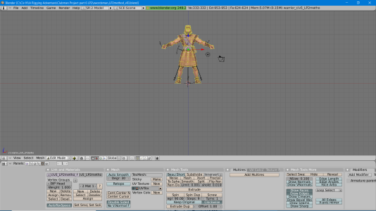
Select your seamed regions, just one or two at a time on the 3D View. Reposition the associated polygons on the desired part of the image in the UV/Image Editor. The same hotkeys work for manipulating the nodes on the UV/Image Editor, as are used on the 3D View. In the window with the textured draw type, you should see the section(s) you are working on acquiring the desired skin. Work through until all of the required faces have had the correct skin applied.
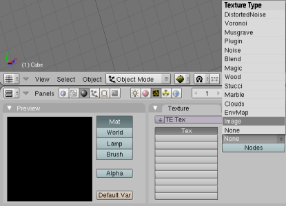
On the Buttons panel, with Shading (F5) (the ball like icon) and Texture buttons (F6 (The yellow and black checkerboard pattern icon), on the Texture tab, click on the dropdown under Texture Type and select Image.

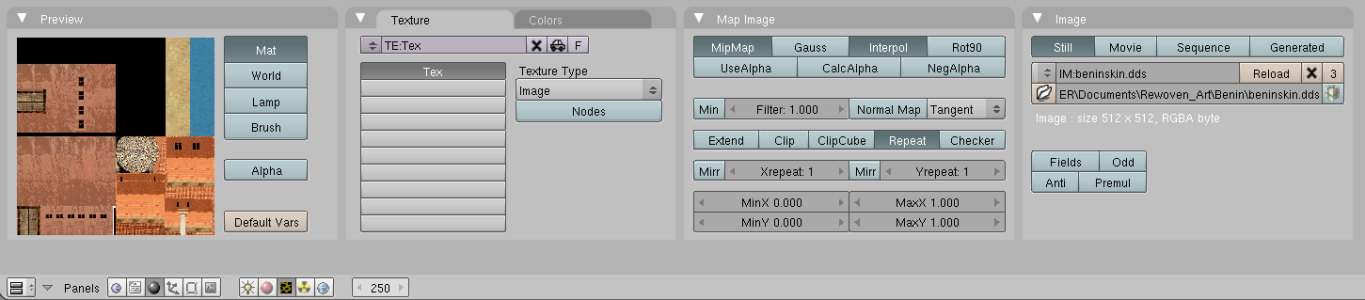
On the Image tab that has now appeared, press Load and then select the image that you are using for the skinning and press SELECT IMAGE.
I'm not an expert at Blender. I've only made a few models and I have to refer back to video tutorials everytime I do. The tutorials I found most helpful in getting going with Blender were Ira Krakow's tutorials for Blender 2.49. This tutorial is as much an aide memoire for me, so I can more quickly do my 3D edits, as it is a tutorial for anyone else.
The Key Hotkeys
These are the main hotkeys that I find myself using when editing (some of these are only going to work when in Edit Mode). I'll probably add to this list, if I do more Blender work.
A Select/Deselect all
B This is used to select specific nodes. Pressing twice will give the little targetting circle and if you press the RMB (right mouse button) you select the nodes within the circle. The circle can be scaled by rolling the MMW (Middle Mouse Wheel). By pressing B once, and then dragging the mouse, while pressing LMB (Left Mouse Button), you can select a rectangle's worth of nodes.
E Extrude. This is used to grow new faces and vertices out from your existing model. Press LMB when finished. This will leave the newly extruded nodes still selected.
G Grab. This is used to move the selected nodes. By default it will move the nodes along the plane of the selected view. By pressing, X, Y or Z after G, you can limit the movement to just along the particular axis. Note: if you select two linked nodes, you are also selecting the associated Edge and if you select multiple linked nodes, you are also selecting the related faces. Press LMB when finished.
H Hide. This hides the selected nodes. This is particularlly handy if you want to make sure you're not accidentally selecting and editing nodes in a part of the model you are not currently wanting to work on.
AltH Show hidden. Reveals the hidden nodes.
R Rotate. By moving the mouse the selected nodes can be rotated in the plane of the view. The X, Y, and Z buttons can be used to define the rotational axis. Press LMB when finished.
S Scale. By moving the mouse this will cause the selected nodes to scale in size bigger or smaller. The X, Y, and Z buttons can be used to limit the scaling along one axis. Press LMB when you've reached the size you want.
U UV Unwrap. Unwraps your model onto the UV/Image Editor. Only use this after you've marked the seams.
W Gives dropdown with a number of options. The ones I've used most are Subdivide and Flip Normals. Flip Normals is what you use when the textured side of a face is facing the wrong way (e.g. the inside of the wall has a texture but the wall is transparent when viewed from outside).
X Delete. Obviously any edges/faces that depend on a node are removed when the node is deleted.
AltM Merge. This is used to combine nodes to minimise the number of polygons that are being used. I usually just merge At Centre. I've found that its helpful to do a sweep through the model before marking the seams for the UV unwrapping and selecting each "node" in turn and merging at it to tidy up those locations where there are multiple nodes co-existing close together.
CtrlE Mark Seam. This is used to define where you want the cuts to be made in the model for the UV unwrapping.
CtrlZ Undo. There isn't an infinite number of undos you can do so remember to save often, when you've made progress you are satisfied with.
1, 3, 7 Used to quickly switch the views to a specific plane in a window.
Most or all of those functions can also be reached by pressing on the Mesh button and working through the dropdown menu. There are additional functions, which I haven't use as much, available there.
Setting up the Views
By moving the mouse to the top of side of a window, and pressing the RMB when the bidirectional arrow appears, you get the option to "Split Area". Press this and then move the grey line to the desired split point and press LMB. This splits the window into two windows.
The windows can be recombined by moving the mouse to the divide between them and pressing the RMB when the bidirectional arrow appears, giving the option to "Join Areas". Select an arrow and press LMB to combine the windows into 1.
When editing, I typically would use two windows in 3D View side by side with the Buttons Window underneath.
Pressing the MMB (Middle Mouse Button) and moving the mouse allows you to rotate the view in a window. The 1, 3 and 7 buttons come in useful here also. Two different views of a model should be enough to get a clear view of what you want to work on.
Editting
Plan what you want the 3d shape to look like.
Select the Edit Mode.
Either use the starting cube to work with or select it and delete it and select an alternative starting mesh.
Select the nodes you want to work on using A or B. Then apply the applicable edit you want to apply; grabbing, rotating, extruding, etc.
One tool which I found particularly useful is the mirror modifier which can halve or quarter the work you need to do.
Select all in Edit Mode (A).
Use F9 to get the buttons window to Editting panel.
Under the Modifier tab, click Add Modifier and select Mirror.
Click the X, Y and/or Z to select the axis around which the object will be mirrored.
Do whatever edits you want mirrored. When finished, click the Apply button on the Modifiers tab.
Skinning
When you have the 3D model in the shape that you want, you'll move on to skinning
I recommend merging nodes where multiple nodes are in the same location. Flip faces if necessary so that the textures are going to be applied on the desired side.
Use CtrlE to mark the seams. These are the lines along which the image will be cut when unwrapped.
Switch one of your windows to UV/Image Editor.
In the 3D View window, in Edit Mode, select All and then unwrap (U). Polygons will appear on the UV/Image Editor.
Note: Only faces that are selected on the 3D View window will be visible on the UV/Image Editor.
Open the image that you are going to use for the skinning. Select Open on the Image dropdown on the UV/Image Editor.
The selected image will appear on the UV/Image Editor.
I found it useful to have an additional window open at this point; so there's 3D View (with Wireframe Draw Type), 3D View (with Textured Draw Type), UV/Image Editor and Buttons Window.
Select your seamed regions, just one or two at a time on the 3D View. Reposition the associated polygons on the desired part of the image in the UV/Image Editor. The same hotkeys work for manipulating the nodes on the UV/Image Editor, as are used on the 3D View. In the window with the textured draw type, you should see the section(s) you are working on acquiring the desired skin. Work through until all of the required faces have had the correct skin applied.
On the Buttons panel, with Shading (F5) (the ball like icon) and Texture buttons (F6 (The yellow and black checkerboard pattern icon), on the Texture tab, click on the dropdown under Texture Type and select Image.
On the Image tab that has now appeared, press Load and then select the image that you are using for the skinning and press SELECT IMAGE.
 Thank you for making this simple, straightforward, and painless.
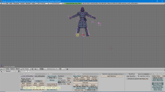


 )
)