Blumonster
Chieftain
- Joined
- Oct 22, 2010
- Messages
- 90
And hey, thanks again for all your help. It's a big relief to even be able to talk to someone about this (I've been trying to figure this skin thing out for four days straight now). 
") No worries. And I know how confusing it is - I remember staring blankly at all the options the first time I did this sort of thing. I made a right pig's ear of it at first
No worries. And I know how confusing it is - I remember staring blankly at all the options the first time I did this sort of thing. I made a right pig's ear of it at first 

Humans, obviously, are not primitives. So you have to UV in stages, selecting a bunch of polygons which approximate one of the projection primitives. So the torso can be UV'ed by projecting a plane from the front onto those polygons.
got past that nasty cube thing.....here is a real old TUT that was very useful from CRoland on UV mapping....
HERE
this is from 2006 so i dont know if the blender functions r the same
So if I'm understanding correctly, basically I'd select all the faces on the front of the torso, for example, and then project a plane onto that selection, which would in effect flatten it out (?) and give it an easy to use rectangular shape (?), which I could then put onto the UV map (?).
Part of the problem with trying to work this out is that I can't find any options in blender to project a plane onto selected polygons. I've looked through the manual, looked online, I don't know if it has the ability to do this...unless, of course, I've missed something or am misunderstanding what you're saying, which is not improbable.


got past that nasty cube thing.....here is a real old TUT that was very useful from CRoland on UV mapping....
HERE
this is from 2006 so i dont know if the blender functions r the same
It's one of these things that will just eventually 'click' and then you'll be scratching your head trying to work out why you were ever so confused, trust me ") )
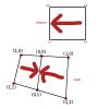
)The way I mapped my prophet was to work with half a mesh. He's horizontally symmetrical, so I only need the left-hand (or right-hand) side of the model. Map that - the head was projected from the side, and then the UVs were pulled around in the UV editor to produce the tweaked layout you can see. When it was all textured, I then duplicated the half-a-mesh, flipped it, and welded it together.
(By the way, there's no "L" in "CaptainBinky" - everybody seems to do this, maybe I should change my name
This is something else I don't quite understand. This is probably a dumb question, but I only see one side of the head in your image file. When you say you duplicated the half, flipped it, and welded it together...where is that in the image?
 ))
))