merijn_v1
Black Belt
Some introduction text that I still have to write.
Requirements
- Blender (make sure you download 2.79. The niftools plugin doesn't work on newer versions)
- niftools blender plugin
- Nifskope
- GIMP with DDS plugin (Or any other image editor which can edit dds files)
0. Installation
- Blender: Follow the Installation instructions
- Niftools blender plugin: You have 2 options, use the auto unpack in Blender tool or unpack manually. (I recommend doing it manually. For me, the auto unpack tool unpacked the file in the roaming appdata instead of in the program files)
Auto unpack
If you don't do this, you get an error when you want to export.
Set the default game to Civ IV.
- GIMP: Follow the installation instructions.
If you have everything set up, we can start working on the art itself.
1. Create mesh
The first thing we will create is a mesh. The mesh is the shape of the building. The best way of learning is to experiment yourself. There are several blender tutorials that explain what the basic functions of blender are. I used this youtube video to get some understanding of the basics in creating a mesh. You can also use my tutorial example to get some basic understanding of the functions of Blender and what comments you should use.
Tutorial example
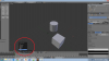
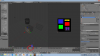
When you start up Blender, you get a default preplaced object (a cube). Your can remove it by pressing the "delete" key. But we will use it as a part of our new building, so we don't do that.
You can rotate the camera by holding the middle-mouse button and move the mouse. If you want to move the camera, press the shift-key and hold the middle-mouse button while moving your mouse.
Using only the default cube isn't very interesting. So we will create some more elements. First, go to the "edit menu". Make sure you are always in this "edit menu" when you create new objects. You can add new objects in the "objects menu", but if you do that, you will get errors when you export to the nif format.

First, deselect the cube by pressing the A key. (The A key deselects all if you have something selected. If you have nothing selected, it will select everything. A selected object will turn orange.)
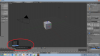
Let's add a simple cylinder. Click the create -> cylinder button. (Red circle in image below) This will create a cylinder at the cursor point. The cursor point is the circle thingy in the blue circle of the image. You can place the cursor point anywhere by left clicking in the main screen. If you want to reset the cursor point to the origin, press shift+s and select "cursor to center".

If you have created a circle, you see a small menu in the bottom left of the screen. You can set certain parameters of the cylinder, such as the radius and the depth. The value "vertices" determines how many points the circle has. You can try some a values and see what happens.
If you set "vertices" to 3, you get a prism. If you set it to 4, you get a cube. The higher the value, the "rounder" the circle becomes. I recommend to use a value that is not too high as that will create more faces. Let's set it to 16 for now.

Let's move the cylinder. There are several methods of moving the cylinder. The first one is by dragging the red, green and blue arrows that appear at the center of the cylinder.
You can also move the cylinder by pressing the G key. After pressing the "G" key, you can move it around with the mouse. If you want to move it only in X, Y or Z direction, press the X, Y or Z key after pressing the G key.
If you want to move the cylinder over a defined distance, you can use the numpad to define the distance. For example, if you press G, X and type 2, the cylinder will move 2 units in the positive X direction.
A third method is by moving the object to a defined location directly. Press N to get the properties menu. You can set the X, Y and Z coordinates at the top of that menu.
For the tutorial, move the cylinder to a place where you want. It doesn't matter if it is connected to the cube or not. I recommend playing a little with it to get an understanding what happens.
You can rescale the cylinder by pressing the S key. Similar to moving around, you can use your mouse to scale the cylinder or use the numpad to define the scale. If you use the numpad, a value of 2 doubles the size and a value of 0.5 halves the size. By pressing the X, Y or Z key you can rescale only 1 axis.
For the tutorial, you can rescale if you want. Play with it a little to see what happens.
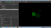
One important thing is that nif files can only deal with faces that have 3 or 4 vertices. The top and bottom of the cylinder have 16 vertices. So we have to make sure this face is split into several smaller faces, all with 3 or for edges. The easiest way is by creating a point in the center and connect all vertices with that one.
First, select the wireframe display.

Now you see the wireframe of the objects. We need to select all vertices of the top of the cylinder. Press B to enable a selection box. Drag the box around all vertices to select all vertices of the top of the cylinder. If all vertices are selected, press the E key to extrude and press the Enter key immediately afterwards. (If you move your mouse you move the extruded vertices, which is undesired)
Now we need to merge the extruded vertices. Click the merge button in the tools menu and select "at center". Deselect all (A key) and repeat the proces for the bottom.

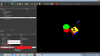
Let's add a final element, a simple plane. First, deselect the cylinder by pressing A. You can add a plane similarly like you added the cylinder, but then with the Plane button ofcourse.
You can resize and move the plane similarly like you did with the cylinder. By default, the plane is horizontal. You can rotate the plane by pressing R and move the mouse around. You can use the X, Y or Z key to rotate around a specific axis. Instead of using the mouse, you can use the numpad to determine the angle. The angle is in degrees.
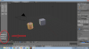
For the tutorial, let's turn the plane 90 degrees around the y-axis. Press R, Y and type 90. Move and rescale the plane as you like.
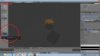
The final result should be something like this.

This is the shape of our new "building". This tutorial explains only some basic functions. I recommend watching this video for some other simple technics and how Blender works in general.
2. Create texture
The texture is an image file with the texture of the building. It defines which colors the objects has. The format for the texture files Civ IV uses is the dds format. There are several programs which can edit dds file. I use the free program GIMP with a dds plugin.
The texture files of buildings usually have 256x256 pixels. Some have 512x256. It is possible to use larger files, but that is not recommended. Smaller files like 128x128 or 64x64 are also possible, but will result in a less detailed texture.
In general not all parts of the texture file will be used. Only certain parts of the texture files will be used. In general, the texture file has a black background to indicate all unused parts of the texture file.
Tutorial Example
Let's say that we want the cube to have 2 blue sides, 2 yellow sides and 2 red sides. The cylinder will have a green top and bottom and red wall. The plane will get some transparent parts and some colored parts, so it will look like a fence.
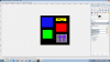
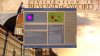
In GIMP, create a new image. Give it a size of 256x256 pixels. Create some areas with the colors, like in the image below. (Use the pencil to (N key)) Add an alpha channel to enable transparency. (Layer->Transparency->Add alpha channel) You can turn some black into transparent area by using the eraser tool or by selecting a rectangle and delete that area.
I created the image below. As you can see, the sizes of colored squares are not equal. I will use this to show that the UV mapping (see next section) can distort the image. The grey chess-pattern is the alpha channel. I painted a small purple fence on it.
Export your image as dds file. (file-> export or ctrl+E) I usually use the "BC2/DXT3" compression. Set the mipmaps option to "Generate Mipmaps".

3. Apply UV mapping
UV mapping is telling the object to uses which part of the texture file for what parts of the object.
Tutorial example
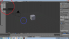
First, we create a new window. This can be done by clicking the lines in the top-right of the main window (red circle) and drag it to the left. Then set the window to UV/Image editor (blue circle)
Open your newly created texture file. (green circle) This will help you determining where you should place the UV maps.

Open the texture menu (red arrow). Select movie or image as texture option (blue arrow). Select the newly created texture file (yellow arrow). Set coordinates to "UV" and map to "UVMap" (green arrow).
This makes sure that the nif files uses the correct texture file.

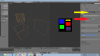
Now we can place the UV map. First, the the display to "face select" (red circle, blue arrow image below) You can select a face by right clicking on one of the points in the middle of the face. Unwrap is by pressing the U key and select "unwrap". You will see the a transparent overlay appearing in the right window. The face will get the texture of the transparent area. We want to make this face blue, so we have to edit the transparent area so it covers only the blue part.
Hover your mouse over the transparent area on the right window and press the L key. This way, you select the area. You can resize the area by pressing the S key and moving your mouse. Also here you can use the X and Y keys and numpad. You can move the area by pressing the G key and moving your mouse. Again, the X and Y key and numpad can be used. The value of the numpad moves the transparent area determines the amount of pixels the transparent area moves.
Alternatively, you can move the vertices of the area. Right-click on the points of the edges of the transparent area to select it. Hold the right mouse button and move your mouse to move the vertices to the desired place. (you can release the right-mouse button when the vertice moves) Left click to select the location of the vertice.
Edit the area so it covers the blue part, like in the image below. In this example, it doesn't matter if the outlines of the transparent area exactly matches the image, because it is a plain area. But if you have a more detailed texture this could matter.

Repeat the proces until all UV maps have been layed down. You can speed up the proces by selecting multiple faces at the same time. Hold shift and right-click. You can also press the B key and select multiple faces in within the box. It is possible that you have to reload the image underlay. This is the green circle of the first image of this section.
Tutorial continues in next post.
Requirements
- Blender (make sure you download 2.79. The niftools plugin doesn't work on newer versions)
- niftools blender plugin
- Nifskope
- GIMP with DDS plugin (Or any other image editor which can edit dds files)
0. Installation
- Blender: Follow the Installation instructions
- Niftools blender plugin: You have 2 options, use the auto unpack in Blender tool or unpack manually. (I recommend doing it manually. For me, the auto unpack tool unpacked the file in the roaming appdata instead of in the program files)
Auto unpack
- In blender, go to file -> user preferences (ctrl-alt-U)
- Go to add-ons and click the "Install Add-ons from file" button (bottom of the screen)
- Navigate to the zip package and select it (usually in you downloads section)
- After installation, don't forget to make sure the checkbox is checked. Save the user preferences.
- Unzip the package in BLENDER_INSTALLATION_LOCATION/Blender/2.79b/Scripts/AddOns (you might need administrator rights for this) My location is: C:\Program Files\Blender Foundation\Blender\2.79\scripts\addons
- In Blender, go to file -> user preferences (ctrl-alt-U)
- Goto Add-Ons and find "Import-Export NetImmerse/Gamebryo nif format" and select the checkbox
- Save user preferences
If you don't do this, you get an error when you want to export.
- Goto the location you installed the nif export tool files.
- Goto FILES_LOCATION\Addons\io_scene_nif\\modules\property\texture\
- Open "texture_export.py" (use a text editor. I use Notepad++ for editing python files.)
- Add the return statement like this (line 225-230)
-
Code:
    def add_shader_integer_extra_datas(self, trishape):
        """Add extra data blocks for shader indices."""
        return
        for shaderindex in self.USED_EXTRA_SHADER_TEXTURES[NifOp.props.game]:
            shadername = self.EXTRA_SHADER_TEXTURES[shaderindex]
            trishape.add_integer_extra_data(shadername, shaderindex)
Set the default game to Civ IV.
- Goto the location you installed the nif export tool files.
- Goto FILES_LOCATION\Addons\io_scene_nif\operators and open "nif_export_op.py".
- Search for the code below (lines 71-82)
-
Code:
    #: For which game to export.
    game = bpy.props.EnumProperty(
        items=[
            (_game_to_enum(game), game, "Export for " + game)
            # implementation note: reversed makes it show alphabetically
            # (at least with the current blender)
            for game in reversed(sorted(
                [x for x in NifFormat.games.keys() if x != '?']))
            ],
        name="Game",
        description="For which game to export.",
        default='CIVILIZATION_IV')
- Change
toCode:
default='OBLIVION')and save the file.Code:default='CIVILIZATION_IV')
- GIMP: Follow the installation instructions.
If you have everything set up, we can start working on the art itself.
1. Create mesh
The first thing we will create is a mesh. The mesh is the shape of the building. The best way of learning is to experiment yourself. There are several blender tutorials that explain what the basic functions of blender are. I used this youtube video to get some understanding of the basics in creating a mesh. You can also use my tutorial example to get some basic understanding of the functions of Blender and what comments you should use.
Tutorial example
When you start up Blender, you get a default preplaced object (a cube). Your can remove it by pressing the "delete" key. But we will use it as a part of our new building, so we don't do that.
You can rotate the camera by holding the middle-mouse button and move the mouse. If you want to move the camera, press the shift-key and hold the middle-mouse button while moving your mouse.
Using only the default cube isn't very interesting. So we will create some more elements. First, go to the "edit menu". Make sure you are always in this "edit menu" when you create new objects. You can add new objects in the "objects menu", but if you do that, you will get errors when you export to the nif format.
Spoiler :
First, deselect the cube by pressing the A key. (The A key deselects all if you have something selected. If you have nothing selected, it will select everything. A selected object will turn orange.)
Let's add a simple cylinder. Click the create -> cylinder button. (Red circle in image below) This will create a cylinder at the cursor point. The cursor point is the circle thingy in the blue circle of the image. You can place the cursor point anywhere by left clicking in the main screen. If you want to reset the cursor point to the origin, press shift+s and select "cursor to center".
Spoiler :
If you have created a circle, you see a small menu in the bottom left of the screen. You can set certain parameters of the cylinder, such as the radius and the depth. The value "vertices" determines how many points the circle has. You can try some a values and see what happens.
If you set "vertices" to 3, you get a prism. If you set it to 4, you get a cube. The higher the value, the "rounder" the circle becomes. I recommend to use a value that is not too high as that will create more faces. Let's set it to 16 for now.
Spoiler :
Let's move the cylinder. There are several methods of moving the cylinder. The first one is by dragging the red, green and blue arrows that appear at the center of the cylinder.
You can also move the cylinder by pressing the G key. After pressing the "G" key, you can move it around with the mouse. If you want to move it only in X, Y or Z direction, press the X, Y or Z key after pressing the G key.
If you want to move the cylinder over a defined distance, you can use the numpad to define the distance. For example, if you press G, X and type 2, the cylinder will move 2 units in the positive X direction.
A third method is by moving the object to a defined location directly. Press N to get the properties menu. You can set the X, Y and Z coordinates at the top of that menu.
For the tutorial, move the cylinder to a place where you want. It doesn't matter if it is connected to the cube or not. I recommend playing a little with it to get an understanding what happens.
You can rescale the cylinder by pressing the S key. Similar to moving around, you can use your mouse to scale the cylinder or use the numpad to define the scale. If you use the numpad, a value of 2 doubles the size and a value of 0.5 halves the size. By pressing the X, Y or Z key you can rescale only 1 axis.
For the tutorial, you can rescale if you want. Play with it a little to see what happens.
One important thing is that nif files can only deal with faces that have 3 or 4 vertices. The top and bottom of the cylinder have 16 vertices. So we have to make sure this face is split into several smaller faces, all with 3 or for edges. The easiest way is by creating a point in the center and connect all vertices with that one.
First, select the wireframe display.
Spoiler :
Now you see the wireframe of the objects. We need to select all vertices of the top of the cylinder. Press B to enable a selection box. Drag the box around all vertices to select all vertices of the top of the cylinder. If all vertices are selected, press the E key to extrude and press the Enter key immediately afterwards. (If you move your mouse you move the extruded vertices, which is undesired)
Now we need to merge the extruded vertices. Click the merge button in the tools menu and select "at center". Deselect all (A key) and repeat the proces for the bottom.
Spoiler :
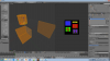
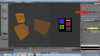
Let's add a final element, a simple plane. First, deselect the cylinder by pressing A. You can add a plane similarly like you added the cylinder, but then with the Plane button ofcourse.
You can resize and move the plane similarly like you did with the cylinder. By default, the plane is horizontal. You can rotate the plane by pressing R and move the mouse around. You can use the X, Y or Z key to rotate around a specific axis. Instead of using the mouse, you can use the numpad to determine the angle. The angle is in degrees.
For the tutorial, let's turn the plane 90 degrees around the y-axis. Press R, Y and type 90. Move and rescale the plane as you like.
The final result should be something like this.
Spoiler :
This is the shape of our new "building". This tutorial explains only some basic functions. I recommend watching this video for some other simple technics and how Blender works in general.
2. Create texture
The texture is an image file with the texture of the building. It defines which colors the objects has. The format for the texture files Civ IV uses is the dds format. There are several programs which can edit dds file. I use the free program GIMP with a dds plugin.
The texture files of buildings usually have 256x256 pixels. Some have 512x256. It is possible to use larger files, but that is not recommended. Smaller files like 128x128 or 64x64 are also possible, but will result in a less detailed texture.
In general not all parts of the texture file will be used. Only certain parts of the texture files will be used. In general, the texture file has a black background to indicate all unused parts of the texture file.
Tutorial Example
Let's say that we want the cube to have 2 blue sides, 2 yellow sides and 2 red sides. The cylinder will have a green top and bottom and red wall. The plane will get some transparent parts and some colored parts, so it will look like a fence.
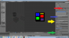
In GIMP, create a new image. Give it a size of 256x256 pixels. Create some areas with the colors, like in the image below. (Use the pencil to (N key)) Add an alpha channel to enable transparency. (Layer->Transparency->Add alpha channel) You can turn some black into transparent area by using the eraser tool or by selecting a rectangle and delete that area.
I created the image below. As you can see, the sizes of colored squares are not equal. I will use this to show that the UV mapping (see next section) can distort the image. The grey chess-pattern is the alpha channel. I painted a small purple fence on it.
Export your image as dds file. (file-> export or ctrl+E) I usually use the "BC2/DXT3" compression. Set the mipmaps option to "Generate Mipmaps".
Spoiler :
3. Apply UV mapping
UV mapping is telling the object to uses which part of the texture file for what parts of the object.
Tutorial example
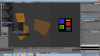
First, we create a new window. This can be done by clicking the lines in the top-right of the main window (red circle) and drag it to the left. Then set the window to UV/Image editor (blue circle)
Open your newly created texture file. (green circle) This will help you determining where you should place the UV maps.
Spoiler :
Open the texture menu (red arrow). Select movie or image as texture option (blue arrow). Select the newly created texture file (yellow arrow). Set coordinates to "UV" and map to "UVMap" (green arrow).
This makes sure that the nif files uses the correct texture file.
Spoiler :
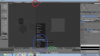
Now we can place the UV map. First, the the display to "face select" (red circle, blue arrow image below) You can select a face by right clicking on one of the points in the middle of the face. Unwrap is by pressing the U key and select "unwrap". You will see the a transparent overlay appearing in the right window. The face will get the texture of the transparent area. We want to make this face blue, so we have to edit the transparent area so it covers only the blue part.
Hover your mouse over the transparent area on the right window and press the L key. This way, you select the area. You can resize the area by pressing the S key and moving your mouse. Also here you can use the X and Y keys and numpad. You can move the area by pressing the G key and moving your mouse. Again, the X and Y key and numpad can be used. The value of the numpad moves the transparent area determines the amount of pixels the transparent area moves.
Alternatively, you can move the vertices of the area. Right-click on the points of the edges of the transparent area to select it. Hold the right mouse button and move your mouse to move the vertices to the desired place. (you can release the right-mouse button when the vertice moves) Left click to select the location of the vertice.
Edit the area so it covers the blue part, like in the image below. In this example, it doesn't matter if the outlines of the transparent area exactly matches the image, because it is a plain area. But if you have a more detailed texture this could matter.
Spoiler :
Repeat the proces until all UV maps have been layed down. You can speed up the proces by selecting multiple faces at the same time. Hold shift and right-click. You can also press the B key and select multiple faces in within the box. It is possible that you have to reload the image underlay. This is the green circle of the first image of this section.
Tutorial continues in next post.
Attachments
-
 Edit_Mode.png284.6 KB · Views: 1,519
 -
 Add_Cylinder.png259.1 KB · Views: 1,374
 -
 Edit_Cylinder.png264 KB · Views: 1,448
 -
 GIMP.png132.8 KB · Views: 1,549
 -
 Wireframe.png257.6 KB · Views: 1,523
 -
 Merge.png291.6 KB · Views: 1,440
 -
 Mesh.png269.1 KB · Views: 1,406
 -
 UVmap.png291.7 KB · Views: 1,498
 -
 UV_Mapping.png261.7 KB · Views: 1,386
 -
 Blue.png278.3 KB · Views: 1,381
Last edited:
")